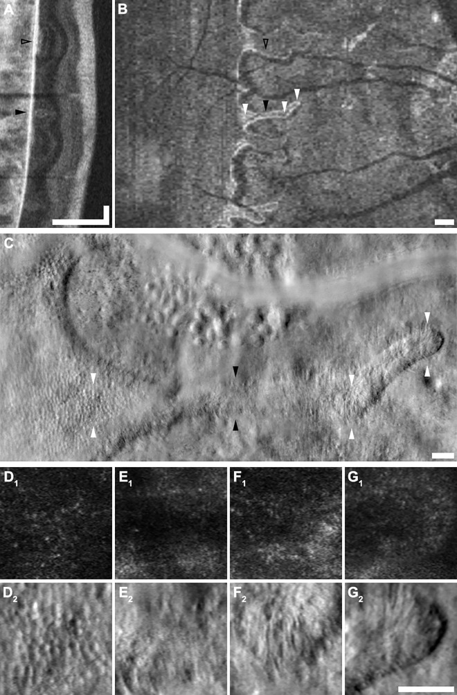
Fig 7. Multimodal imaging of ORTs.
A-G present a vertical SD-OCT B-scan (A), an en face SD-OCT projection (B), a split-detector AOSLO montage (C), and zoomed-in views of the montage (D-G) of an ORT in subject JC_0778. Labeled arrowheads indicate corresponding locations in different modalities. The ORT indicated by the filled black arrowhead is structurally distinct on B-scan (A) from the wider patch of preserved retina just superior (indicated by the open black arrowhead). Top and bottom arrowheads in C indicate the top and bottom edges of the zoomed-in 100 x 100 μm images provided by panels D to G. Relatively normal cones are seen in the region of preserved retina (D) while sparse, morphologically abnormal remnant cone inner segments are seen throughout the ORT (E, F, G). Scale bars: A, lateral (vertical) & axial (horizontal) = 250 μm, axial (horizontal) = 100 μm; B, 250 μm; C, 50 μm; D-G, 50 μm.

