Abstract
Purpose:
To present a novel brachytherapy technique, called multihelix rotating shield brachytherapy (H-RSBT), for the precise angular and linear positioning of a partial shield in a curved applicator. H-RSBT mechanically enables the dose delivery using only linear translational motion of the radiation source/shield combination. The previously proposed approach of serial rotating shield brachytherapy (S-RSBT), in which the partial shield is rotated to several angular positions at each source dwell position [W. Yang et al., “Rotating-shield brachytherapy for cervical cancer,” Phys. Med. Biol. 58, 3931–3941 (2013)], is mechanically challenging to implement in a curved applicator, and H-RSBT is proposed as a feasible solution.
Methods:
A Henschke-type applicator, designed for an electronic brachytherapy source (Xoft Axxent™) and a 0.5 mm thick tungsten partial shield with 180° or 45° azimuthal emission angles and 116° asymmetric zenith angle, is proposed. The interior wall of the applicator contains six evenly spaced helical keyways that rigidly define the emission direction of the partial radiation shield as a function of depth in the applicator. The shield contains three uniformly distributed protruding keys on its exterior wall and is attached to the source such that it rotates freely, thus longitudinal translational motion of the source is transferred to rotational motion of the shield. S-RSBT and H-RSBT treatment plans with 180° and 45° azimuthal emission angles were generated for five cervical cancer patients with a diverse range of high-risk target volume (HR-CTV) shapes and applicator positions. For each patient, the total number of emission angles was held nearly constant for S-RSBT and H-RSBT by using dwell positions separated by 5 and 1.7 mm, respectively, and emission directions separated by 22.5° and 60°, respectively. Treatment delivery time and tumor coverage (D90 of HR-CTV) were the two metrics used as the basis for evaluation and comparison. For all the generated treatment plans, the D90 of the HR-CTV in units of equivalent dose in 2 Gy fractions (EQD2) was escalated until the D2cc (minimum dose to hottest 2 cm3) tolerance of either the bladder (90 Gy3), rectum (75 Gy3), or sigmoid colon (75 Gy3) was reached.
Results:
Treatment time changed for H-RSBT versus S-RSBT by −7.62% to 1.17% with an average change of −2.8%, thus H-RSBT treatments times tended to be shorter than for S-RSBT. The HR-CTV D90 also changed by −2.7% to 2.38% with an average of −0.65%.
Conclusions:
H-RSBT is a mechanically feasible delivery technique for use in the curved applicators needed for cervical cancer brachytherapy. S-RSBT and H-RSBT were clinically equivalent for all patients considered, with the H-RSBT technique tending to require less time for delivery.
Keywords: rotating shield brachytherapy, intensity modulated brachytherapy, cervical cancer, electronic brachytherapy, multihelix rotating shield brachytherapy
1. INTRODUCTION
Cervical cancer treatment with external beam radiotherapy (EBRT), concurrent chemotherapy, and magnetic resonance (MR) image guided intracavitary brachytherapy with supplemental interstitial brachytherapy (IS+ICBT) has been shown to be superior to EBRT, chemotherapy, and intracavitary brachytherapy (ICBT) alone.1 In the Vienna series, pelvic control (cervix, uterine corpus, vagina, parametric, and lymph nodes) at 3 yr for patients with bulky tumors of >5 cm increased remarkably from 63% at 3 yr to 90%. This followed the introduction of MR-enabled IS+ICBT dose escalation to the high-risk clinical target volume (HR-CTV)2 using GEC-ESTRO guidelines, simultaneous cisplatin chemotherapy, and laparoscopic pelvic node dissection with macroscopic removal for the majority of the patients in the most recent series. Although it is unclear what percentage of the observed improvement in pelvic control is attributable to the use of MR-enabled IS+ICBT alone, there is little doubt that the resulting dose escalation played an important role in obtaining such positive results. For patients with smaller residual tumors (<5 cm), the advantage of the IS+ICBT approach is reduced as obtaining HR-CTV tumor dose conformity with ICBT is possible.
A key capability in the Vienna series was the ability to deliver IS+ICBT. Forty-four percent (69 of 156) of the patients had unfavorable spread of residual disease, and the majority of those cases were treated with the Vienna tandem and ring applicator, which can be used for the positioning of supplementary interstitial brachytherapy needles.3,4 A challenge with adoption of IS+ICBT for cervical cancer is that few physicians are trained in its delivery and it is more invasive than ICBT alone. Delivering ICBT alone, however, has the disadvantage that the radiation source emits a radially symmetric dose distribution and is constrained to travel inside an intracavitary applicator. When treating a large, laterally extended HR-CTV with nearby organs at risk (OARs) such as bladder, rectum, and sigmoid colon, these geometric restrictions limit the achievable dose escalation. Potential alternatives to IS+ICBT for cervical cancer that would be dosimetrically superior to ICBT alone have been proposed, including rotating shield brachytherapy (RSBT)5–8 and direction-modulated brachytherapy (DMBT).9 With RSBT as proposed for cervical cancer,5–8 an electronic brachytherapy (eBx) source (Xoft Axxent™, iCAD, Inc., Nashua, NH, USA) with a rotating partial shield travels down an intracavitary applicator, and the amount of radiation delivered in a given direction is modulated by controlling the amount of time the aperture created by the shield points in that direction. With DMBT for cervical cancer,9 a multichannel applicator with a MR-compatible, photon-attenuating tungsten core is proposed, and the directional modulation is achieved by controlling the dwell time of the 192Ir radiation source at each dwell position.
The focus of the current work is on presenting multihelix RSBT (H-RSBT), a mechanically feasible RSBT delivery technique. With H-RSBT, only linear translational motion of the radiation source/shield combination is necessary for the delivery, simplifying the process relative to serial RSBT (S-RSBT). In previous work,6 it was demonstrated that S-RSBT, in which the partial shield is rotated to 16 angular positions at each 5-mm-spaced dwell position, has the potential to provide equivalent or superior HR-CTV D90-values comparable to those of IS+ICBT for a range of different HR-CTV shapes and applicator positions, under the same OAR constraints to the bladder, rectum, and sigmoid colon. However, the authors have been unsuccessful at developing a S-RSBT system that has the potential to operate safely with curved applicators due to the mechanical challenge of accurately rotating a radiation shield about a fixed dwell position inside a curved applicator. The H-RSBT technique, in which the partial shield is rotated to six angular positions at each 1.7-mm-spaced dwell position, is designed to overcome the obstacles to S-RSBT implementation, enabling the delivery of deliberately nonsymmetric, tumor-conformal dose distributions that would be impossible to deliver with conventional, unshielded, radiation sources in intracavitary applicators.
2. MATERIALS AND METHODS
2.A. Brachytherapy source
A partially shielded Xoft Axxent™ eBx source10 is considered as the brachytherapy source, which is a miniature x-ray source that is sheathed in a 5.4 mm diameter water-cooled catheter. The tube can be operated between 20 and 50 kVp, at a standard operating voltage of 50 kV and tube current of 300 μA. The air-kerma strength of an eBx source is 1.4 kGy/h. The eBx source is driven by a remote afterloading device (control console), which is a robot that can control the location of the source inside the applicator to better than ±1 mm resulting in providing the desired longitudinal translation. The controller unit is also equipped with a pullback arm which has three adjustable joints allowing a desired longitudinal translation and better positioning and alignment of the source through a channel or applicator in order to provide a proper-shaped dose distribution.
2.B. Applicator and shield design
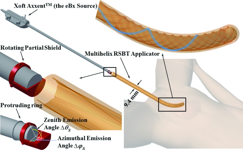
A novel applicator/shield/source system (Fig. 1) with an outer diameter of 9.4 mm was designed to enable RSBT dose delivery for cervical cancer. Based on H-RSBT technique, the direction of a partial radiation shield is controlled using only translational motion of the radiation source. This is an advantageous property, as the eBx system already provides accurate translational motion capability, enabling the system to be extended to accommodate RSBT delivery without the addition of rotational motors, simplifying the implementation process.
FIG. 1.
Multihelix rotating shield brachytherapy (H-RSBT) system.
The common applicator shape for cervical cancer brachytherapy, shown in Fig. 1, has a curved central (tandem) applicator that can be substituted for tandem applicators with different curvatures depending on the patient and day. The H-RSBT applicator is an intracavitary tandem-type intrauterine applicator that is inserted past the cervix and into the patient’s uterus. It contains six evenly spaced helical keyways, which provide pathways that the keys from the shield follow when the source is translated. The rotating shield attaches to the end of the eBx catheter and rotates freely about the catheter inside the applicator. The shield has three uniformly distributed protruding keys on it, which occupy three of those six keyways at a given time. The position of the source in the applicator dictates the direction of the radiation shield and therefore the irradiation direction, thus H-RSBT only requires translational motion of the brachytherapy source inside the applicator for the shield to rotate. Since the clinical eBx unit already has a translational drive, no additional motors would be needed to deliver H-RSBT. The keyways, as shown in Fig. 1, start at the proximal entrance to the straight part of the applicator with a loose pitch (15 cm/rotation) that increases linearly to the desired pitch (3.33 cm/rotation) at the curved part of the applicator. This approach enables a smooth mechanical transition of the shield from the straight to the curved part of the applicator.
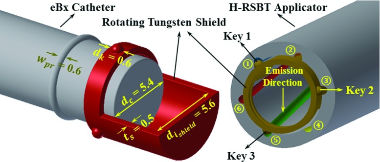
An important feature of the H-RSBT applicator shown in Fig. 1 is that it contains six loosely wound helical keyways that are longitudinally offset from each other. A cross section of the applicator is shown in Fig. 2. Multiple keyways are required when they are loosely wound since using only a single keyway would not provide enough emission angles per unit applicator length to deliver dose distributions that are competitive with S-RSBT. Having six keyways increases the number of shield emission angles per centimeter, enabling an improvement in the deliverable dose distributions. By setting source travel per rotation of the keyways to 3.33 cm, H-RSBT dose distributions have the potential to be equivalent to S-RSBT dose distributions, as the number of emission angles per centimeter for H-RSBT is approximately the same as that for S-RSBT. Thus, H-RSBT and S-RSBT create 36.6 and 35.4 emission angles/cm of source travel inside the patient, respectively.
FIG. 2.
Cross section of H-RSBT applicator and shield. All dimensions are in millimeter.
Clinical H-RSBT delivery would proceed as follows. The entire H-RSBT delivery would be done using one or more shields each with three protruding keys attached on its surface. For the first (of six) delivery segments, the shield keys #1, #2, and #3 would occupy keyways #1, #3, and #5, respectively, as shown in Fig. 2. The source would travel to the distal end of the applicator, stopping along the way at discrete longitudinal/angular dwell positions for preset dwell times. After the first segment, the source and shield could be retracted and reinserted with the shield keys occupying a second combination of keyways, which would be keyways #2, #4, and #6, respectively. This proceeds until all of the desired combinations of keyways have been used for the delivery.
The shield used in the H-RSBT system must rotate about the radiation source smoothly and unimpeded during the dose delivery procedure. Therefore, a connection between the shield and the water-cooling catheter surrounding the eBx source is needed. As shown in Fig. 1, in order to attach the shield to the eBx catheter such that it rotates freely, it is proposed to remanufacture the cooling catheter such that it has a protruding circumferential plastic ring that can be used to hold the shield in place. Further, as shown in Fig. 2, the tungsten shield thickness is 500 μm, which is enough to provide less than 0.1% dose transmission, while still rotating freely about the water-cooling catheter. As the partially shielded cylinder is not curved and will remain a straight cylinder through the whole procedure, the inner diameter of the applicator is restricted in terms of the magnitude of both length and thickness of the shield.
2.C. Source trajectory and shield emission direction
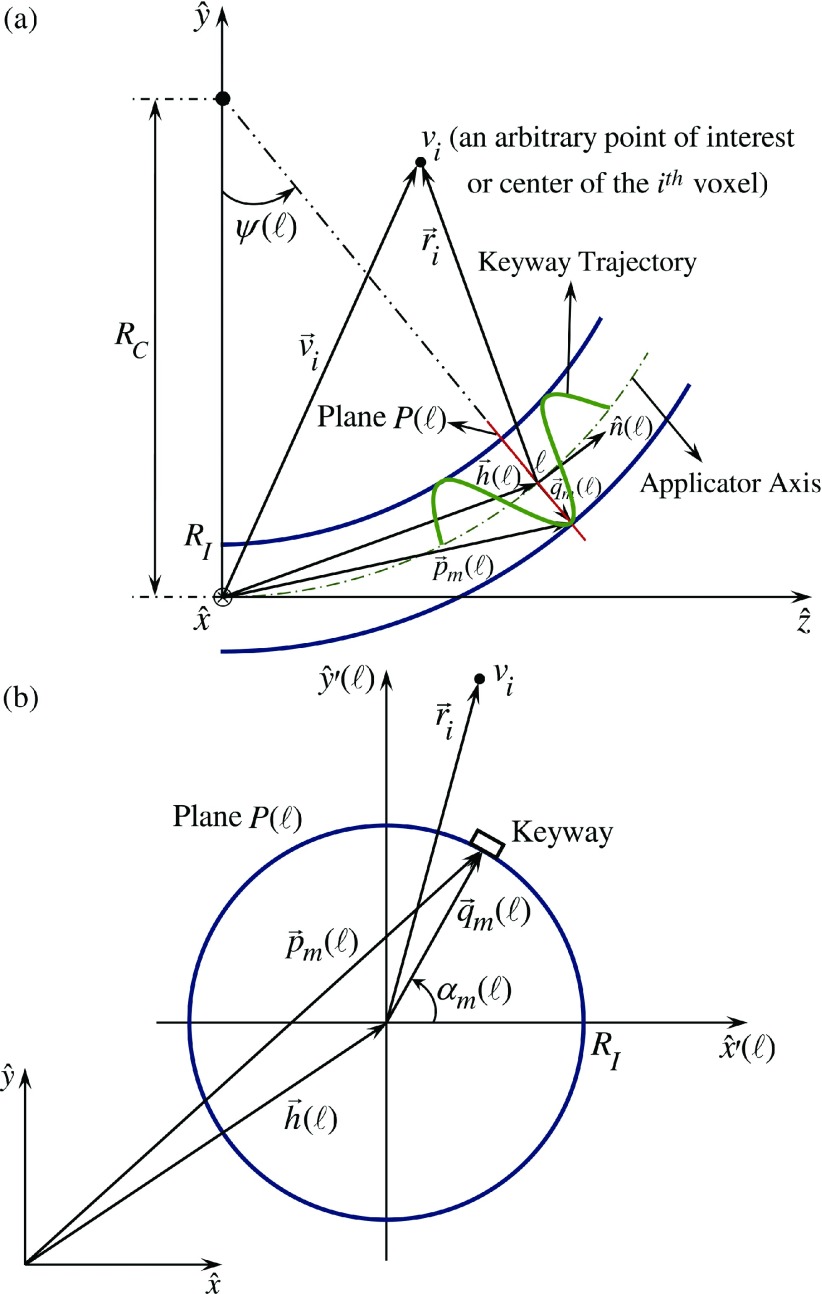
A Henschke-style applicator can be modeled as a straight tube and an attached arc with a radius of curvature of RC. Figures 3(a) and 3(b) show the geometrical parameters of a single helical keyway on a single dwell position in global and local coordinate systems, respectively. According to it, assume the following: RI is the interior radius of the applicator, is applicator axis located in 3-D space at position ℓ along the applicator axis, is angle of the keyway m at position ℓ in the applicator while m = 1, 2, …, 6, ℓr is the source travel per one rotation of a keyway inside the curved part of the applicator, and is the 3-D spatial location of the center of the entrance to the keyway m at position ℓ along the applicator. In general, the location of the entrance to keyway m at position ℓ is
| (1) |
where is the vector between the applicator axis at position ℓ and the inner applicator wall at keyway m, defined in the coordinate system [Fig. 3(b)] as
| (2) |
and is defined as
| (3) |
Thus, is calculated as
| (4) |
FIG. 3.
Multihelix RSBT applicator trajectory geometry and related parameters and coordinates.
2.D. Patients and dose prescription
Five patients with cervical cancer staging from IB to IVA were considered in an Institutional Review Board approved study. As shown in Table I, HR-CTV volumes ranged from 42.2 to 98.8 cm3 (mean 68.1 cm3, standard deviation 23.8 cm3) and HR-CTV extents ranged from 6.3 to 9.6 cm (mean 7.9 cm, standard deviation of 1.8 cm). All the CTVs and OARs were manually contoured by physicians on T2-weighted 1 × 1 × 3 mm-resolution MR images taken with a Siemens MAGNETOM 3T scanner (Siemens, Germany) at the beginning of the first fraction of brachytherapy. A titanium Fletcher-Suit-Delclos style tandem and ovoids (Varian Medical Systems, Palo Alto, CA) were used as the brachytherapy applicator. The same datasets were used for the current study as by Yang et al.6
TABLE I.
HR-CTV volumes and dimensions for all patients considered.
| HR-CTV volume (cm3) | HR-CTV maximum dimension (cm) | |
|---|---|---|
| Patient #1 | 42.2 | 6.3 |
| Patient #2 | 45.8 | 7.4 |
| Patient #3 | 78.0 | 8.6 |
| Patient #4 | 98.8 | 9.6 |
| Patient #5 | 75.0 | 7.5 |
| Average | 68.0 | 7.9 |
| Standard deviation | 23.8 | 1.8 |
| Range | [42.2–98.8] | [6.3–9.6] |
All patients received external beam radiation therapy in 25 fractions at 1.8 Gy/fraction. It was assumed for all the cases that the external beam radiotherapy dose was uniformly delivered in the HR-CTV and OARs. The dose in each voxel was converted to equivalent dose as given in 2 Gy-fractions (EQD2) using the linear quadratic model11 where the linear-quadratic parameter, α/β, set to 3 Gy for the OARs and 10 Gy for the HR-CTV.
Based on the institutional standard, the brachytherapy dose was simulated to be delivered over five fractions. For all the generated brachytherapy treatment plans, the EQD2 of the HR-CTV was escalated until the EQD2 D2cc tolerance of any of the three OARs was reached. The OAR’s tolerances were in accordance with those defined by Groupe Européen de Curiethérapie, European Society for Therapeutic Radiology and Oncology (GEC ESTRO): 90 Gy3 for bladder, and 75 Gy3 for rectum and sigmoid colon.2,12
2.E. Dose calculation and treatment planning
A modified form of the American Association of Physicists in Medicine Task Group 43 (TG-43)13 technique was applied as the basis for RSBT dose calculation according to
| (5) |
in which is the dose rate at point with the origin at the center of the eBx point source, where (Fig. 3),
| (6) |
and m is an index standing for the angular course of the shield opening pointed in azimuthal direction φm = (m − 1) δφ, where m = 1, ..., 16, and m = 1, …, 6 for S-RSBT and H-RSBT, respectively, and δφ = 22.5∘ and δφ = 60∘ for S-RSBT and H-RSBT, respectively. In Eq. (5), Sk is the air-kerma strength of the eBx source, which is 1.4 × 10⁵ U according to Rivard et al.,14 Λ is the dose-rate constant, which is 0.495 cGy U−1 h−1 based on Pike,15 is the geometry function, is a reference point at distance 1 cm lateral from the core of the source, is the anisotropy function, and is the shield transmission function which is defined as
| (7) |
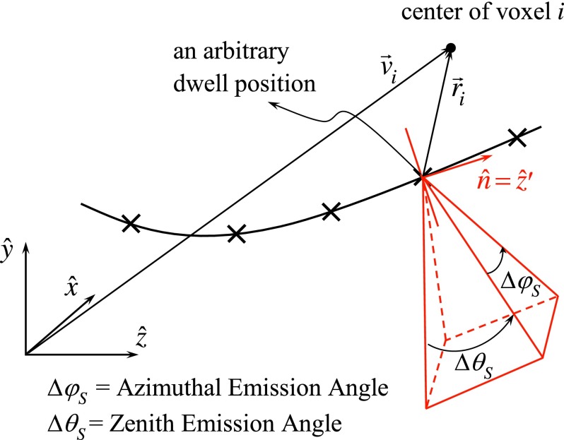
where , , , and are, respectively, defined in the coordinate system (Figs. 3 and 4) as
| (8) |
| (9) |
| (10) |
| (11) |
As shown by Eq. (7), is set to zero when is obscured by the shield and unity otherwise. As the transmission of the 500 μm thick tungsten shield is less than 0.1%, the transmission factor is simply taken to be zero in this study. The radial dose and anisotropy functions for the eBx source were obtained from Rivard et al.14 as well.
FIG. 4.
Geometry of a pyramid-shaped beam produced by a cone shield.
In order to ensure a fair comparison between treatment plans of H-RSBT and S-RSBT, the number of RSBT beamlets7 in H-RSBT is set equal to that in S-RSBT with the assumption that a RSBT beamlet is defined as the dose rate at a point of interest due to a shielded radiation source at a specific dwell position. This uniformity is achieved by decrease of dwell position spacing from 5 mm in S-RSBT to 1.7 mm in H-RSBT and accordingly an increase in the number of H-RSBT dwell positions of over a factor of 2.6. Further, the gradient-based linear least squares method from Shepard et al.16 was exploited to optimize the dwell times of the dose rate distributions for each beamlet.
2.F. Evaluation
HR-CTV D90, HR-CTV V100, and total treatment time are the metrics used to evaluate all treatment plans for both S-RSBT and H-RSBT echniques. Two azimuthal shield emission angles of 45° and 180° were considered for all patients. According to Dimopoulos et al.,17,18 in cervical cancer patients treated with the combination of EBRT and brachytherapy, the local tumor control probability improves significantly when HR-CTV D90 is set to 87 Gy or more. In addition, the HR-CTV V100, the percentage HR-CTV volume receiving a dose of 100 Gy EQD2, was measured as the basis to assess the extent of the HR-CTV hot spots. The total treatment time was also calculated and reported as the total time in which the radiation source positioned inside the patient was irradiating the tumor and did not include the time necessary to reposition the source shield in the keyways when changing emission angles between segments.
3. RESULTS
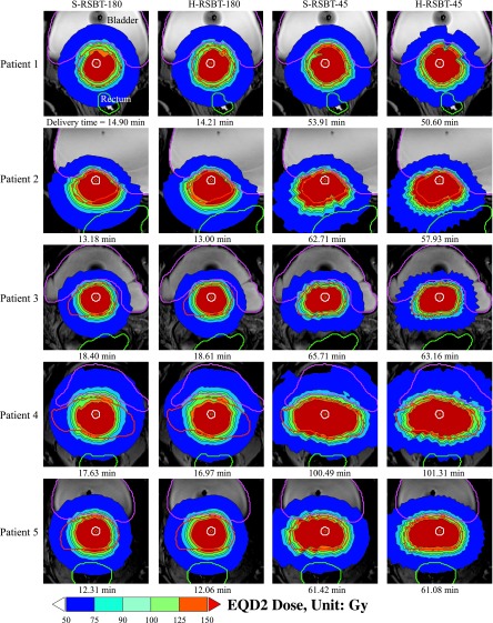
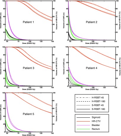
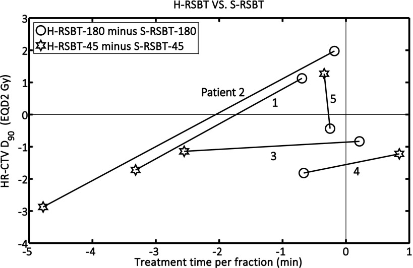
The EQD2 distributions and corresponding dose–volume histograms (DVHs) for all five patients are shown in Figs. 5 and 6, respectively. Figure 7 shows the D90 and the treatment time differences of H-RSBT relative to S-RSBT for the two azimuthal emission angles: 45° and 180°. Patients 4 and 5 almost had negligible treatment time differences between H-RSBT and S-RSBT. For patient 3, the D90 differences were nearly the same for both 45° and 180° azimuthal emission angles and were around 1 Gy. H-RSBT in patients 1 and 2 had reduced treatment times relative to S-RSBT for both 45° and 180° azimuthal emission angles. Figure 5 shows that the HR-CTV V100 values for treatment plans with 45° azimuthal emission angle are substantially higher than those with 180° azimuthal emission angle in both S-RSBT and H-RSBT.
FIG. 5.
Dose distributions for the cervical cancer patients considered. S-RSBT-45/180: serial rotating shield brachytherapy using either a 45° or a 180° azimuthal emission angle; H-RSBT-45/180: helical rotating shield brachytherapy using either a 45° or a 180° azimuthal emission angle.
FIG. 6.
Dose–volume histograms for all treatment plannings considered for all five patients. S-RSBT-45/180: serial rotating shield brachytherapy using either a 45° or a 180° azimuthal emission angle; H-RSBT-45/180: helical rotating shield brachytherapy using either a 45° or a 180° azimuthal emission angle; HR-CTV: high-risk clinical target volume.
FIG. 7.
D90 and treatment time differences for H-RSBT relative to S-RSBT for both 45° and 180° azimuthal emission angles. S-RSBT-45/180: serial rotating shield brachytherapy using either a 45° or a 180° azimuthal emission angle; H-RSBT-45/180: helical rotating shield brachytherapy using either a 45° or a 180° azimuthal emission angle; HR-CTV: high-risk clinical target volume.
As shown in Fig. 7, the D90 tolerances between H-RSBT and S-RSBT were at most ±2.5%. Also, the treatment time differences were approximately in the range of −7% to 1%. The range of delivery times, shown in Fig. 5, for H-RSBT with the 180° and 45° azimuthal emission angles was 12.06–18.61 min and 50.6–101.31 min, respectively. Thus, the 45° azimuthal emission angle plans would require over four times as long to deliver as the 180° emission angle plans. The average treatment time decrease per fraction of H-RSBT relative to S-RSBT for all patients was 2.8%. The average D90 decrease of H-RSBT relative to S-RSBT was clinically irrelevant, at 0.65%.
4. DISCUSSION
In order to facilitate a straightforward dosimetric comparison, the dose distributions shown in Fig. 5 were generated using HR-CTV dose escalation in which the HR-CTV D90 is maximized until the D2cc EQD2 constraint on either of three OARs is reached. In clinical practice, the physician may prefer to compromise OAR sparing in order to avoid underdosing the tumor, or stop the dose escalation once a prescribed HR-CTV D90 has been reached, thus delivering OAR doses that are all below tolerance.
H-RSBT and S-RSBT have similar dose conformity, but the treatment time of H-RSBT is approximately 3% less than that of S-RSBT. Further, the DVHs (Fig. 6) demonstrate that H-RSBT and S-RSBT techniques have D90 values within ±2.5% for the HR-CTV and D2cc values within ±3.5% for the three OARs. Dose distributions generated with the 45° azimuthal angle shield are more conformal to the HR-CTV than those generated with the 180° azimuthal shield, but at the expense of a considerable increase in the treatment time of over a factor of four. This fact is directly due to the difference in emission window which controls the amount of energy per unit time at each dwell position. The HR-CTV D90, treatment time, and HR-CTV V100 were greater on average for RSBT-45 than RSBT-180 by factors of 1.3, 4.5, and 1.1, respectively. As shown in Fig. 7, H-RSBT provided a shorter treatment time than S-RSBT for eight of those ten treatment plans. However, their D90 values decreased except for three treatment plans. In general, H- or S-RSBT-45 methods provide HR-CTV D90 benefit relative to those plans with 180° azimuthal emission angle.
The HR-CTV V100 values were high compared to those values of common 192Ir-based ICBT techniques. This can lead to a uterine overdose. This effect is mainly due to both source specifications and the RSBT treatment time. The dose from the eBx source is proportional to the inverse cube radial distance from the source while that from 192Ir sources is proportional to the inverse square of the radius. Further, the treatment time in RSBT is increased compared to the common ICBT techniques in order to guarantee the tumor coverage. Greater irradiation time is corresponding to a greater dose in the tissues around the source. However, the maximum tolerable hot spots in cervical cancer brachytherapy are not clear due to lack of clinically relevant data.
In the clinical application of H-RSBT for cervical cancer, one has to employ all the six combinations of keys and keyways engagements (as shown in Fig. 2 and explained in Sec. 2.B) in order to make sure of the tumor irradiation coverage. Delivering H-RSBT with an apparatus that enables the retraction and reinsertion of the source/shield in order the shield keys to occupy all of the six combinations of keyways in an automatically changing fashion would accomplish the automation of all of the clinical implementation steps of H-RSBT technique and would improve dosimetric radiation and tumor conformity and also reduce the treatment time. Another advantage of H-RSBT in terms of clinical implementation is its flexibility to adapt to a given patient’s cancer stage and shape of the tumor. Based on each patient’s cervical cancer stage and the GTV invasion shape, a set of optimal shield with specific zenith and azimuthal emission angles and a set of optimal dwell times needs to be employed.
An additional benefit of H-RSBT is that a shield angle monitoring system is not necessary, as shield angle is parameterized by translational position. There is a drawback to this, however, as uncertainty in shield emission angle is proportional to uncertainty in longitudinal source position. As the longitudinal eBx source position is known to within the standard ±1 mm and the designed shield rotates once every 33.3 mm, then the shield emission angle is only known to within (±1mm) (360°/33.3 mm) = ±10.8°. A sensitivity analysis was performed to determine the dosimetric impact of such errors, which is summarized in Table II for the two extreme cases of −1 and +1 mm of systematic longitudinal positioning errors. For each patient, only one OAR tolerance dose was violated when a ±1 mm systematic shift occurred. HR-CTV underdose always occurred, and the underdose ranged from 2% to 16%. The observed dosimetric changes resulting from the longitudinal positioning uncertainty represent extreme cases, as positional uncertainty will have both random and systematic components which, combined with fractionation of the deliveries over five sessions will have a dose-blurring effect, reducing the overall dosimetric uncertainty. Once a prototype system is developed, the random and systematic source positioning uncertainties can be quantified and a more realistic sensitivity analysis performed. It may also be warranted to develop a robust or worst-case optimization technique for H-RSBT that generates dose distributions that are relatively intensive to the worst-case dwell position errors.
TABLE II.
Effects of systematic longitudinal source positioning errors on dose to the HR-CTV, and organs at risk for 45° azimuthal emission angle. Only the organ-at-risk D2cc values for which the D2cc tolerance was violated following the positioning errors were included. Organ-at-risk tolerance D2cc-values for sigmoid colon, rectum, and bladder were 75, 75, and 90 Gy3, none of which were violated when there is no positioning error.
| Patient | Longitudinal positioning error (mm) | HR-CTV D90 change (%) | Sigmoid colon D2cc (Gy3) | Rectum D2cc (Gy3) | Bladder D2cc (Gy3) |
|---|---|---|---|---|---|
| 1 | −1 | −2.15 | 76.18 | ||
| +1 | −2.07 | 93.26 | |||
| 2 | −1 | −6.31 | 97.89 | ||
| +1 | −6.17 | 98.24 | |||
| 3 | −1 | −3.54 | 75.89 | ||
| +1 | −3.4 | 75.97 | |||
| 4 | −1 | −15.67 | 78.71 | ||
| +1 | −5.18 | 102.24 | |||
| 5 | −1 | −6 | 75.62 | ||
| +1 | −4.96 | 105.8 |
The H-RSBT system has the flexibility in using different shields with different geometrical specifications in a single treatment plan. As there are already six different combinations of keys and keyways and all of them have to be accounted for, different shields can be employed in different combinations. One can use up to six different shields with different azimuthal and zenith emission directions to enhance the D90 values and reduce the treatment time provided that a professional optimizer defines the related parameters in advance. However, this capability of H-RSBT technique has not been explored yet. Furthermore, in some cases which are of less locally advanced cervical tumor, all of those six keys and keyways combinations might be redundant and those can be reduced to three. This can lead to a decrease in treatment time.
Accurate applicator reconstruction in the treatment planning system based on MR imaging is critical in order to minimize spatial uncertainty in the longitudinal position of the applicator, which would translate to uncertainty in the azimuthal direction of the rotating shield. As the applicator reconstruction would be template-based, a key need will be accurately localizing the applicator tip. Effective quantification of the applicator tip positioning accuracy using MR imaging will not be possible until the applicator is constructed, and enabling submillimeter applicator reconstruction accuracy is an important design consideration.
5. CONCLUSIONS
H-RSBT is a mechanically feasible technique in the curved applicators needed for cervical cancer brachytherapy. S-RSBT and H-RSBT dose distributions were clinically equivalent for all patients considered, with the H-RSBT deliveries tending to be faster.
ACKNOWLEDGMENT
Research reported in this publication was supported in part by the National Institute of Biomedical Imaging and Bioengineering of the National Institutes of Health under award number R01EB020665. The content is solely the responsibility of the authors and does not necessarily represent the official views of the National Institutes of Health.
REFERENCES
- 1.Potter R., Georg P., Dimopoulos J. C., Grimm M., Berger D., Nesvacil N., Georg D., Schmid M. P., Reinthaller A., Sturdza A., and Kirisits C., “Clinical outcome of protocol based image (MRI) guided adaptive brachytherapy combined with 3D conformal radiotherapy with or without chemotherapy in patients with locally advanced cervical cancer,” Radiother. Oncol. 100, 116–123 (2011). 10.1016/j.radonc.2011.07.012 [DOI] [PMC free article] [PubMed] [Google Scholar]
- 2.Potter R., Haie-Meder C., Van Limbergen E., Barillot I., De Brabandere M., Dimopoulos J., Dumas I., Erickson B., Lang S., Nulens A., Petrow P., Rownd J., Kirisits C., and Group G. E. W., “Recommendations from gynaecological (GYN) GEC ESTRO working group (II): Concepts and terms in 3D image-based treatment planning in cervix cancer brachytherapy-3D dose volume parameters and aspects of 3D image-based anatomy, radiation physics, radiobiology,” Radiother. Oncol. 78, 67–77 (2006). 10.1016/j.radonc.2005.11.014 [DOI] [PubMed] [Google Scholar]
- 3.Dimopoulos J. C., Kirisits C., Petric P., Georg P., Lang S., Berger D., and Pötter R., “The Vienna applicator for combined intracavitary and interstitial brachytherapy of cervical cancer: Clinical feasibility and preliminary results,” Int. J. Radiat. Oncol., Biol., Phys. 66, 83–90 (2006). 10.1016/j.ijrobp.2006.04.041 [DOI] [PubMed] [Google Scholar]
- 4.Kirisits C., Lang S., Dimopoulos J., Berger D., Georg D., and Pötter R., “The Vienna applicator for combined intracavitary and interstitial brachytherapy of cervical cancer: Design, application, treatment planning, and dosimetric results,” Int. J. Radiat. Oncol., Biol., Phys. 65, 624–630 (2006). 10.1016/j.ijrobp.2006.01.036 [DOI] [PubMed] [Google Scholar]
- 5.Liu Y., Flynn R. T., Kim Y., and Wu X., “Asymmetric dose-volume optimization with smoothness control for rotating-shield brachytherapy,” Med. Phys. 41, 111709 (11pp.) (2014). 10.1118/1.4897617 [DOI] [PubMed] [Google Scholar]
- 6.Yang W., Kim Y., Wu X., Song Q., Liu Y., Bhatia S. K., Sun W., and Flynn R. T., “Rotating-shield brachytherapy for cervical cancer,” Phys. Med. Biol. 58, 3931–3941 (2013). 10.1088/0031-9155/58/11/3931 [DOI] [PubMed] [Google Scholar]
- 7.Liu Y., Flynn R. T., Yang W., Kim Y., Bhatia S. K., Sun W., and Wu X., “Rapid emission angle selection for rotating-shield brachytherapy,” Med. Phys. 40, 051720 (12pp.) (2013). 10.1118/1.4802750 [DOI] [PMC free article] [PubMed] [Google Scholar]
- 8.Liu Y., Flynn R. T., Kim Y., Yang W., and Wu X., “Dynamic rotating-shield brachytherapy,” Med. Phys. 40, 121703 (11pp.) (2013). 10.1118/1.4828778 [DOI] [PMC free article] [PubMed] [Google Scholar]
- 9.Han D. Y., Webster M. J., Scanderbeg D. J., Yashar C., Choi D., Song B., Devic S., Ravi A., and Song W. Y., “Direction-modulated brachytherapy for high-dose-rate treatment of cervical cancer. I: Theoretical design,” Int. J. Radiat. Oncol., Biol., Phys. 89, 666–673 (2014). 10.1016/j.ijrobp.2014.02.039 [DOI] [PubMed] [Google Scholar]
- 10.Dickler A. and Dowlatshahi K., “Xoft Axxent electronic brachytherapy,” Expert Rev. Med. Devices 6, 27–31 (2009). 10.1586/17434440.6.1.27 [DOI] [PubMed] [Google Scholar]
- 11.Joiner M. and Kogel A.v.d., Basic Clinical Radiobiology (Hodder Arnold, London, 2009), pp. 102–119. [Google Scholar]
- 12.Haie-Meder C., Potter R., Van Limbergen E., Briot E., De Brabandere M., Dimopoulos J., Dumas I., Hellebust T. P., Kirisits C., Lang S., Muschitz S., Nevinson J., Nulens A., Petrow P., Wachter-Gerstner N., and G.E.C.E.W.G. Gynaecological, “Recommendations from gynaecological (GYN) GEC-ESTRO working group (I): Concepts and terms in 3D image based 3D treatment planning in cervix cancer brachytherapy with emphasis on MRI assessment of GTV and CTV,” Radiother. Oncol. 74, 235–245 (2005). 10.1016/j.radonc.2004.12.015 [DOI] [PubMed] [Google Scholar]
- 13.Nath R., Anderson L. L., Luxton G., Weaver K. A., Williamson J. F., and Meigooni A. S., “Dosimetry of interstitial brachytherapy sources: Recommendations of the AAPM Radiation Therapy Committee Task Group No. 43. American Association of Physicists in Medicine,” Med. Phys. 22, 209–234 (1995). 10.1118/1.597458 [DOI] [PubMed] [Google Scholar]
- 14.Rivard M. J., Davis S. D., Dewerd L. A., Rusch T. W., and Axelrod S., “Calculated and measured brachytherapy dosimetry parameters in water for the Xoft Axxent x-ray source: An electronic brachytherapy source,” Med. Phys. 33, 4020–4032 (2006). 10.1118/1.2357021 [DOI] [PubMed] [Google Scholar]
- 15.Pike T. L., A Dosimetric Characterization of an Electronic Brachytherapy Source in Terms of Absorbed Dose to Water (University of Wisconsin, Madison, WS, 2012). [Google Scholar]
- 16.Shepard D. M., Olivera G. H., Reckwerdt P. J., and Mackie T. R., “Iterative approaches to dose optimization in tomotherapy,” Phys. Med. Biol. 45, 69–90 (2000). 10.1088/0031-9155/45/1/306 [DOI] [PubMed] [Google Scholar]
- 17.Dimopoulos J. C., Lang S., Kirisits C., Fidarova E. F., Berger D., Georg P., Dorr W., and Pötter R., “Dose-volume histogram parameters and local tumor control in magnetic resonance image-guided cervical cancer brachytherapy,” Int. J. Radiat. Oncol., Biol., Phys. 75, 56–63 (2009). 10.1016/j.ijrobp.2008.10.033 [DOI] [PubMed] [Google Scholar]
- 18.Dimopoulos J. C., Pötter R., Lang S., Fidarova E., Georg P., Dorr W., and Kirisits C., “Dose–effect relationship for local control of cervical cancer by magnetic resonance image-guided brachytherapy,” Radiother. Oncol. 93, 311–315 (2009). 10.1016/j.radonc.2009.07.001 [DOI] [PubMed] [Google Scholar]


