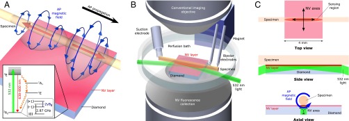
Fig. 1.
Experimental overview. (A) Schematic image depicting bipolar azimuthal magnetic field associated with AP propagating from left to right. Red arrows indicate axial current through axon, and blue arrows depict associated magnetic field. Magnetic field projection is detected by 13-μm-thick NV layer on diamond substrate. (Inset) NV center energy level diagram; see SI Appendix for details. (B) Custom-built microscope allows simultaneous magnetic sensing and conventional imaging of specimens. NV centers are excited by 532-nm laser light oriented at grazing incidence to diamond top surface. Inverted aspheric condenser objective collects NV LIF. Magnet applies a uniform 7-G bias field to the diamond. Specimens are placed on top of diamond, and individual APs are stimulated by suction electrode and detected downstream via a pair of bipolar recording electrodes. For clarity, wire loop for MW delivery and axon clamp are not shown. (C) Top, side, and axial views of NV diamond sensor and specimen. Top view shows sensing region from which LIF is collected, as well as top-down projection of the four crystallographic NV axes. AP magnetic field projects onto two NV axes perpendicular to specimen axis. Side view shows 532-nm laser light entering diamond at grazing angle and exciting NV layer. Blue arrow in axial view depicts AP magnetic field; black arrows depict NV axes in sensing region.

