Significance
Direct solar desalination, which produces desalinated water directly using solar energy with minimum carbon footprint, is considered a promising technology to address the global water scarcity. Here, we report a solar desalination device, with efficient two-dimensional water supply and suppressed thermal loss, which can enable an efficient (80% under one-sun illumination) and effective (four orders salinity decrement) solar desalination. The energy transfer efficiency of this foldable graphene oxide film-based device fabricated by a scalable process is independent of water quantity and can be achieved without optical or thermal supporting systems, therefore significantly improving the scalability and feasibility of this technology toward a complementary portable and personalized water solution.
Keywords: graphene oxide, solar steam, 2D water path, solar desalination, heat localization
Abstract
Because it is able to produce desalinated water directly using solar energy with minimum carbon footprint, solar steam generation and desalination is considered one of the most important technologies to address the increasingly pressing global water scarcity. Despite tremendous progress in the past few years, efficient solar steam generation and desalination can only be achieved for rather limited water quantity with the assistance of concentrators and thermal insulation, not feasible for large-scale applications. The fundamental paradox is that the conventional design of direct absorber−bulk water contact ensures efficient energy transfer and water supply but also has intrinsic thermal loss through bulk water. Here, enabled by a confined 2D water path, we report an efficient (80% under one-sun illumination) and effective (four orders salinity decrement) solar desalination device. More strikingly, because of minimized heat loss, high efficiency of solar desalination is independent of the water quantity and can be maintained without thermal insulation of the container. A foldable graphene oxide film, fabricated by a scalable process, serves as efficient solar absorbers (>94%), vapor channels, and thermal insulators. With unique structure designs fabricated by scalable processes and high and stable efficiency achieved under normal solar illumination independent of water quantity without any supporting systems, our device represents a concrete step for solar desalination to emerge as a complementary portable and personalized clean water solution.
As water scarcity (1, 2) becomes one of most pressing global challenges of our time, efficient solar desalination could provide a promising solution to produce clean water directly out of solar energy without extra energy input, particularly urgent for developing countries and remote areas without basic infrastructures (3–5). With rapid development in the past few years (6–16), it is clear that there are two key elements to enable efficient solar desalination: broadband and efficient solar absorption and localized heat management for efficient vapor generation with minimized parasitic thermal loss. So far, significant progress has been made on both of these fronts. Absorbers with various rational designs have been demonstrated with efficient solar absorption (11, 14, 15). Also, from dispersed particles (6, 7, 16), to porous carbon film (8, 9), to thin metallic absorbers (10, 11, 14, 15), there is a clear trend to confine the absorbed energy in a thinner region for localized heating and more-efficient vapor generation, to minimize dissipated heat to the environment and bulk water. Impressive high-energy transfer efficiency has been achieved, but only for a limited amount of solution, with the assistance of both concentrators and thermal insulation.
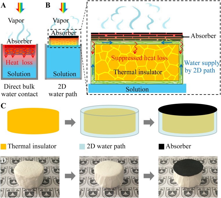
Efficient and effective solar desalination independent of water quantity under normal one-sun illumination without extra supporting systems will fundamentally improve the scalability and feasibility of this technology. However, there is an intrinsic barrier that prevents all of the current designs from achieving this goal. As shown in Fig. 1A, in most if not all of the current designs, the absorbers are always in direct contact with bulk water, i.e., “direct bulk water contact,” to ensure that the absorbed solar energy can be efficiently transferred to bulk water to generate vapors. However, even with advanced heat localization designs with all of the other parasitic heat loss minimized, bulk water itself (with thermal conductivity around 0.5 W/mK) becomes an intrinsic and dominant thermal conduction path. A significant portion of the absorbed energy will unavoidably dissipate through bulk water, evidenced by undesirable temperature elevation of bulk water (Fig. 1A) (see Table S1 for the detailed calculation); this is the reason that, for all of these direct bulk water contact designs, high efficiency can only be achieved for rather limited water quantity with increased solar irradiation (using optical concentrators) and thermal insulation, as the heat loss through bulk water can only be minimized under these rather strict conditions. For the same reason, the efficiency of solar desalination will decrease dramatically with increased water quantity, as the heat loss to bulk water increases correspondingly, fundamentally constraining its scalability.
Fig. 1.
Schematics and a process flow. (A) Schematics of conventional solar steam generation with direct water contact. (B) Schematics of solar desalination devices with suppressed heat loss and 2D water supply. (C) Flowchart for the fabrication of solar desalination devices: polystyrene foam, cellulose coating, and GO film on top surface. (D) (Left) The physical map of polystyrene foam (thermal insulator), (Middle) cellulose (2D water path) wrapped over the surface of polystyrene foam, and (Right) GO film (absorber) on the top surface.
Table S1.
Percentage of conduction loss to bulk water out of the input solar power for solar steam systems with various temperature differences and thicknesses of absorbers
| Absorber thickness, mm | Conduction loss, % | ||||
| 1 °C difference | 5 °C difference | 10 °C difference | 15 °C difference | 20 °C difference | |
| 1 | 50 | — | — | — | — |
| 5 | 10 | 50 | — | — | — |
| 10 | 5 | 25 | 50 | 75 | — |
| 15 | 3.33 | 16.67 | 33.33 | 50 | 66.67 |
| 20 | 2.5 | 12.5 | 25 | 37.5 | 50 |
Here we demonstrate that, when water path is confined to be two dimensional (2D), both efficient water supply and suppressed heat loss can be achieved simultaneously. As shown in Fig. 1B, the absorber, a graphene oxide (GO) film in the experiment, is not in direct contact with bulk water. Instead, they are physically separated by a thermal insulator (a polystyrene foam, thermal conductivity of ∼0.04 W/mK) to ensure much suppressed parasitic heat loss (Fig. 1B, zoom-in). A 2D water path is enabled by a thin layer of cellulose wrapped over the surface of the thermal insulator (Fig. 1 C and D). Because the entire structure can float naturally on the surface of water, with only the bottom side of cellulose in direct contact with bulk water, an efficient water supply to the absorber on the top surface can be enabled by a 2D surface water path within the cellulose pumped by capillary force. Different from “bulk water supply,” because of reduced dimensionality of water path, the heat dissipation through water will be minimized (Fig. 1B). Therefore, with a 2D surface water path, both efficient water supply and suppressed parasitic heat dissipation can be achieved simultaneously.
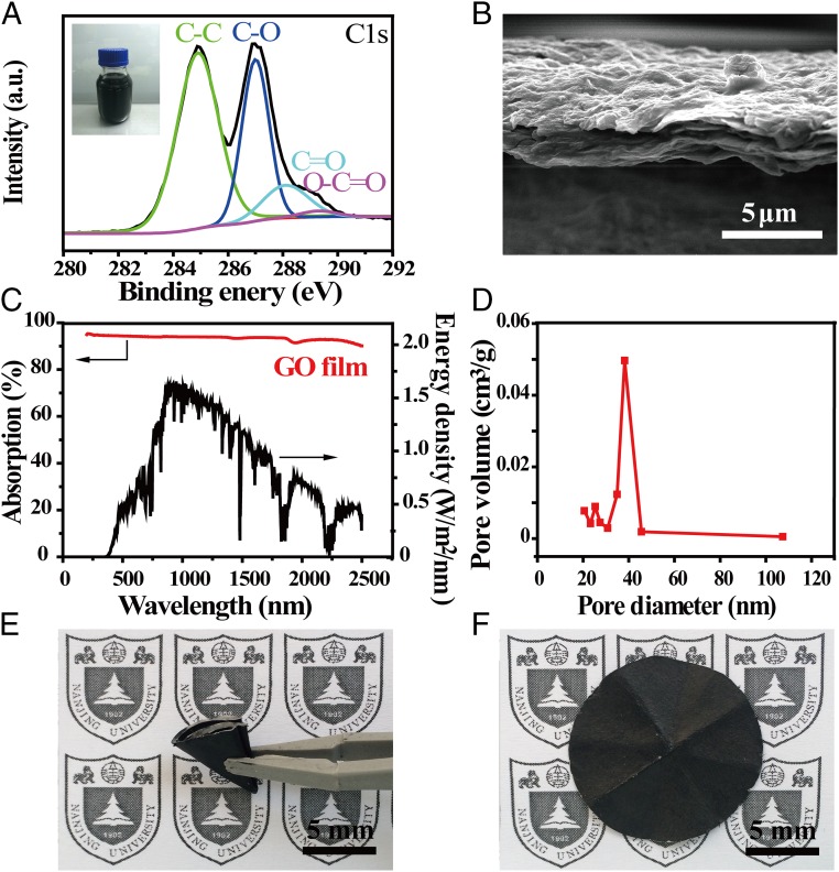
GO film, a derivative of graphene (17–21), is chosen as the absorber of the solar desalination device for several reasons. First, GO film fabricated by a low-cost and scalable process is an efficient and broadband absorber. Second, it is well known that GO film has porous structures, which can provide an efficient path for water supply and vapor flow (22–30). Third, the cross-plane thermal conductivity of GO film is very low (∼0.2 W/mK) (31, 32), beneficial for suppressing the parasitic thermal dissipation. Fourth, GO film is highly foldable and can be naturally attached to cellulose (33, 34), so that the water pumped by capillary force within the cellulose can be efficiently transferred to GO film. Each of these properties is carefully examined below. Fig. 2A shows the X-ray photoelectron spectroscopy result of GO film, prepared by Hummers’ method (35). The 1s peak of carbon (C1s) of GO film mainly consist of four types of carbon bonds (36, 37): C−C in aromatic rings at ∼284.9 eV, C−O (hydroxyl and epoxy) at ∼286.9 eV, C=O (carbonyl) at ∼288.1 eV, and O−C=O (carboxyl) at ∼289.3 eV. GO film with these functional groups shows excellent hydrophilicity, and therefore can be stably dispersed in aqueous solution (Fig. 2A, Inset), feasible for low-cost and scalable spray-coating (38, 39) or spin-coating (40) processes. Fig. 2B shows a clear layered structure of GO film (about 4 μm thick) after vacuum filtration. The absorption of GO film was carefully measured from 200- to 2,500-nm wavelength using the UV-visible spectroscopy. As shown in Fig. 2C, GO film has efficient and broadband absorption, with ∼94% weighted by standard solar spectrum of air mass 1.5 global (AM 1.5 G). To enable efficient solar steam generation, absorbers also need to provide efficient paths for water supply and escaping vapor (22–30). As shown in Fig. 2D, the pore size existing in GO film, carefully examined by Brunauer−Emmett−Teller (BET) test, is about 40 nm, due to defect-etching strategy (41). In addition, our GO film also shows excellent foldability. As shown in Fig. 2E, the GO film can be folded over 50 times without causing notable damages once unfolded (Fig. 2F). This excellent foldability is particularly beneficial for carriage and deployment of large-scale solar desalination.
Fig. 2.
Characterizations of GO film. (A) XPS general spectra and curve fitting of C1s spectra of GO film. (Inset) The optical image of GO solution. (B) The cross-sectional image of the GO film. (C) The absorption spectra of the GO film in the wavelength range of 250 nm to 2,500 nm, weighted by standard AM 1.5 G solar spectrum. (D) The pore size distribution of GO film. (E) The optical image of a folded GO film. (F) The optical image of an unfolded GO film after folding over 50 times.
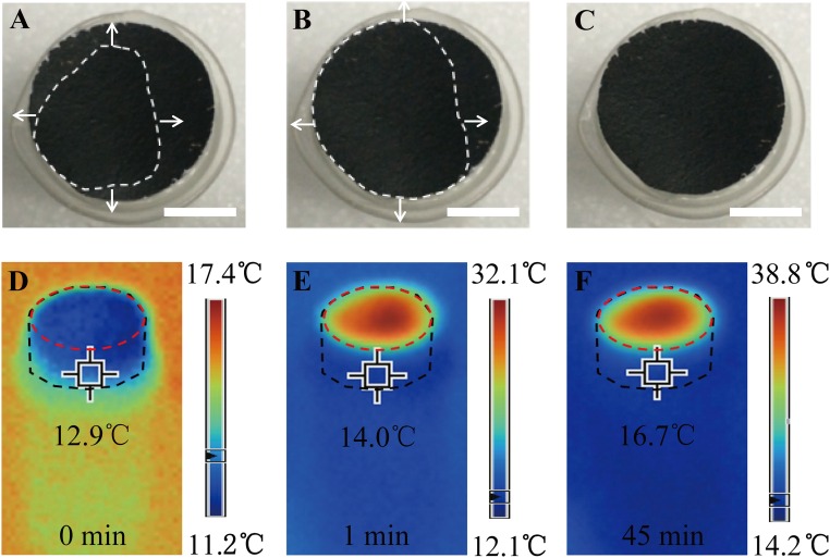
As mentioned above, a polystyrene foam (1.6 cm thick, thermal conductivity of ∼0.04 W/mK; Shengnuoda Material Co., Ltd.) is used as the thermal insulating layer between the absorber (GO film) and bulk water. A thin (∼50 μm) hydrophilic cellulose can be conveniently wrapped over the surface of polystyrene foam to provide a 2D water path. To show the efficient water supply of this 2D water path, Fig. S1 A−C capture the top view of the wetting process once cellulose-wrapped polystyrene foam is put on the surface of water. It is clear that cellulose-wrapped polystyrene foam can float naturally on the surface of solution. From the top view, it is noted that the area closest to the sidewalls got wet first, as water was pumped by capillary force through the 2D water path on the sidewalls within the cellulose (Fig. S1A). The wet area spread toward the center of the surface (Fig. S1B) very quickly until it covered the entire top surface (Fig. S1C) of the cellulose. Fig. 3 A−C shows the wetting process once GO film is placed on the upper surface of the cellulose-wrapped polystyrene foam. Because it is expected that water can easily get into the GO film due to its hydrophilicity, naturally, water will come up from the initial touching point (Fig. 3A), and then quickly spread out (Fig. 3B) until it covers the entire surface of GO film (Fig. 3C). Therefore, it is clear that the absorbers (GO film) can be fed with continuous water flow by this 2D water path without direct contact with bulk water.
Fig. S1.
Wetted area on top surface of cellulose over time [(A) 0 s, (B) 3 s, (C) 5 s] as water is supplied within 2D water path by capillary force (the red dashed lines represent the parts that are not yet wet; the arrows indicate the direction of water flow). (Scale bars, 5 mm.)
Fig. 3.
Water supply by capillary force and temperature distribution within solar desalination devices. (A−C) Wetted area of GO film over time once GO film is put on the top surface (the white dashed lines represent the wet parts; the arrows indicate the direction of water flow). (Scale bars, 5 mm.) (D−F) Temperatures of the GO film and the cellulose-wrapped polystyrene foam (2D water path) over irradiation time. Beakers (without any thermal insulation) are used in this experiment (the black dashed lines represent the approximate edges of the cellulose-wrapped polystyrene foam; the red dashed lines represent the approximate edges of the GO film).
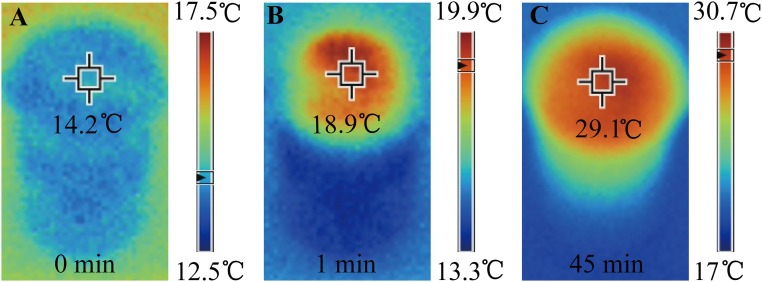
Because the water path is confined to be 2D on the surface of thermal insulators, heat loss from absorbers to bulk water and other environments is significantly suppressed. Fig. 3 D−F shows the temperatures of the GO film and the cellulose-wrapped polystyrene foam over time under one-sun irradiation. To demonstrate the suppressed heat loss to bulk water, a common beaker was used without any extra thermal insulation such as a Dewar container. It can be seen that, with the design of the 2D water path, the absorbed energy was highly localized on the GO film; the central temperature of GO film increased from 12.9 °C to 32.1 °C very quickly (within 1 min), and stabilized at about 38.8 °C (after 45 min). Because the 2D water path enables much suppressed heat loss, there is no significant temperature increase in other parts of the system. As a direct indication, the temperature on sidewalls of the cellulose only changed about 3.8 °C after the irradiation for 45 min, as shown in Fig. 3F. In comparison, if the GO film is in direct contact with bulk water, the central temperature of GO film only increased from 14.4 °C to 19.9 °C in 1 min, and finally stabilized at about 30.7 °C (as shown in Fig. S2 A−C).
Fig. S2.
The temperatures of the GO film and the bulk water over time [(A) 0 min, (B) 1 min, and (C) 45 min] with the direct bulk water contact design using a beaker as a container.
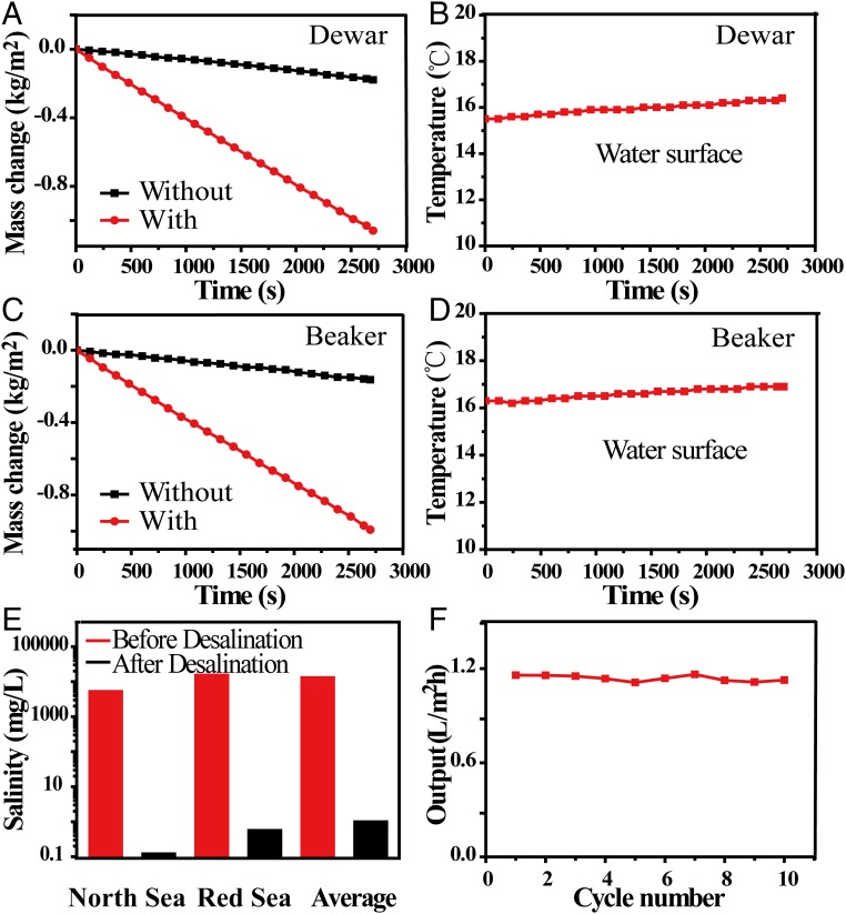
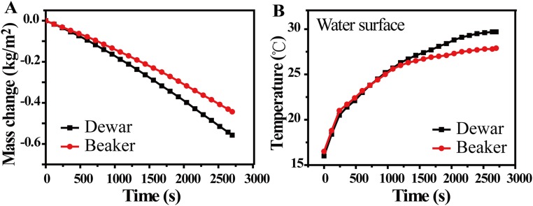
To systematically evaluate the energy transfer efficiency of our solar desalination device, the evaporation rates are first measured by recording the weight change over time under normal solar illumination (1 kW/m2) within a thermal insulated system (Dewar container). As shown in Fig. 4A, the evaporation rates of our device and pure water are 1.45 kg⋅m−2⋅h−1 and 0.24 kg⋅m−2⋅h−1, respectively. The formula η = ṁhLV/Pin is used for calculating the efficiency (η) (8), in which ṁ is the mass flux, hLV is total liquid−vapor phase-change enthalpy (sensible heat + phase-change enthalpy), and Pin is the received power density of the solar irradiation on the absorber surface. The energy transfer efficiency with 2D water path can reach 80%, which is much higher than the 50% of the one with direct water contact (Fig. 2A). (Fig. S3A). The much suppressed heat loss in our design can also be confirmed by the temperature changes of the water surface. As shown in Fig. 4B, the temperature of the water surface has risen only by 0.9 °C with the 2D water path design, much lower than the 13.7 °C in the case of direct bulk water contact (Fig. S3B). Because of much suppressed heat loss and therefore reduced water temperature increase, our device can achieve 78% energy transfer efficiency (see Heat Loss for detailed calculation), without any thermal insulation (beaker instead of Dewar container) (as shown in Fig. 4C), much higher than the 39% achieved in GO-based direct bulk water contact designs under the same conditions (Fig. S3A). The temperature of the water surface has risen only by 0.6 °C (as shown in Fig. 4D), which is much lower than the 11.4 °C in the case of direct bulk water contact (Fig. S3B). It should be also noted that, different from most of the previous studies, there is a linear mass change over irradiation time (a few hundred seconds) as shown in Fig. 4 A and C, which is also a direct indication of much reduced heat loss and therefore reduced time to reach steady state.
Fig. 4.
The performance of devices under solar illumination. (A) Mass changes over time with and without samples with 2D water path using Dewar containers. (B) Temperature changes of steam and bulk water over time using Dewar containers. (C) Mass changes over time with and without devices with 2D water path using beaker containers. (D) Temperature changes of steam and bulk water over time using beaker containers. (E) Measured salinities of three simulated sea water samples, North Sea (1.4 wt%), Red Sea (4.1 wt%), and global average salinity (3.5%) before (red) and after (black) desalination. (F) Evaporation cycle performance of solar desalination devices over 10 cycles, with each cycle sustained over 1 h using beaker containers.
Fig. S3.
(A) The mass change of water with GO film under 1-kW/m2 solar illumination. (B) The temperature changes of underlying bulk water over time under irradiation with the direct bulk water contact design.
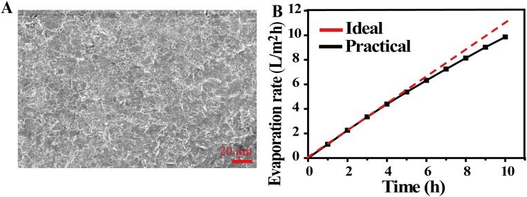
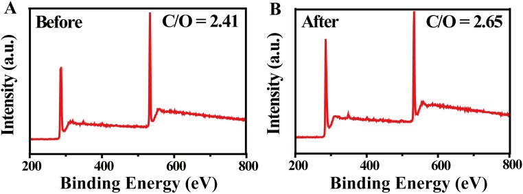
To carefully examine the effect of desalination, three water samples with representative simulated salinities, north sea (salinity 1.4%), red sea (salinity 4.1%), and averaged salinity of the sea (salinity 3.5%), were used and carefully tracked by inductively coupled plasma spectroscopy (ICP–OES, 0.1 mg/L in accuracy, PTIMA 5300 DV; PerkinElmer Instrument). (more experimental details are provided in Methods). As can be seen from Fig. 4E, after desalination, the sodium ions decreased from 5,200 mg/L, 1,5228 mg/L, and 13,000 mg/L to 0.12 mg/L, 0.99 mg/L, and 0.56 mg/L, respectively, far below drinking water standards (200 mg/L) (42, 43). As shown in Fig. 4F, stable performance of our device over 10 cycles is demonstrated, with each cycle lasting for 1 h using beakers without any thermal insulation. Although a little salt can precipitate on the surface of GO film (which can be easily washed away by sea water), there is no obvious change in the morphology of GO film after 10 cycles (Fig. S4), and the ratio of carbon and oxygen of GO film has not changed after 24 h of work under one sun (Fig. S5).
Fig. S4.
(A) The SEM image of GO film after washing (after 10 cycles). (B) Evaporation rate over time with the 2D water path device using beaker containers (salinity 3.5%).
Fig. S5.
The XPS survey of GO film (A) before and (B) after working 24 h under one sun.
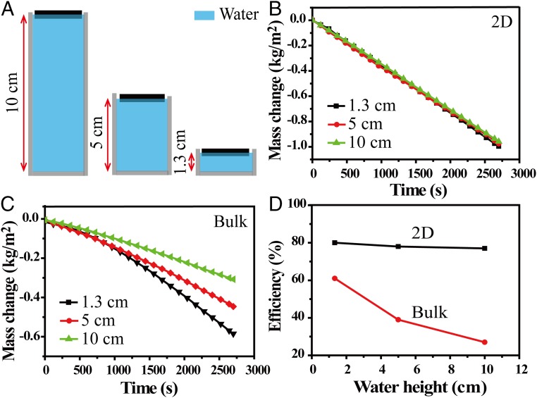
More strikingly, this “2D water path” design with suppressed heat loss can enable stable energy transfer efficiency with much reduced dependence on water quantity. We carefully examine the dependence of efficiencies on water quantity for the 2D water path device and the one with direct bulk water contact, as shown in Fig. 5A. With increased water quantity, from 7 mL (corresponding to 1.3 cm in height) to 53 mL (10 cm in height), the efficiency of our device is kept to ∼80%, as shown in Fig. 5 B and D. In comparison, with increased water quantity, the efficiency of the device with direct bulk water contact decreases dramatically from 61% to 27%, as the heat loss to bulk water increases significantly, as shown in Fig. 5 C and D.
Fig. 5.
The performance of devices with different water quantity. (A) Schematics of devices using beakers with the same diameter (∼2.6 cm) but different water height; 1.3 cm, 5 cm, and 10 cm in height correspond to 7 mL, 26.5 mL, and 53 mL in volume, respectively. (B) Mass changes over time with the 2D water path device using different water quantity. (C) Mass changes over time with direct bulk water contact device using different water quantity. (D) The dependence of the efficiency on the water quantity, for 2D water path (black curve) and direct bulk water contact (red curve).
Conclusions
In summary, enabled by a unique design of 2D water path, we demonstrate an efficient and effective solar desalination device under one sun, with stable performance independent of water quantity without supporting systems of thermal insulators and optical concentrators. This entire device is based on low-cost materials and scalable processes, therefore providing a complementary portable water solution, particularly beneficial for developing countries and remote areas (see Comparison Between Our Solar Desalination for details). The design concept of a 2D water path also provides a general guideline for advanced thermal management and water supply, which is critical for many other potential applications, such as sterilization and chemical purification.
Methods
Fabrication Processes of Solar Desalination Devices.
For the fabrication of GO film, GO was prepared from graphite powder by a modified Hummers’ method. The graphite oxide was filtered and washed with 1:10 hydrochloric acid aqueous solutions followed by water cleaning to remove the acid until the pH of solution became neutral. The 0.4 g of graphite oxide was dispersed in 100 mL of deionized water by ultrasonication for 3 h to make an aqueous dispersion. Then, 3 mL of GO solution at the concentrations of 4 mg/mL was deposited onto a porous mixed cellulose membrane filter (50 mm in diameter, 0.02-mm pore size) to form a GO film through vacuum filtration followed by vacuum drying at 60 °C for 5 h.
For thermal insulators with a 2D water path, ∼1.6-cm-thick polystyrene foam was chosen as the thermal insulating layer. Hydrophilic cellulose was wrapped over the surface of polystyrene foam to make sure that the water could reach the upper surface of the polystyrene foam by capillary force.
Characterizations of GO Film.
The morphologies and structures of the GO film were characterized by scanning electron microscopy (SEM) (Dual-beam FIB 235; FEI Strata). The atomic ratios of carbon to oxygen and the existence of functional groups of GO film were characterized using the X-ray photoelectron spectroscopy (XPS) (PHI 5000 VersaProbe), equipped with a monochromatic Al Ka X-ray source operated in a residual vacuum of 5 × 10⁻⁹ Torr. The absorption of wet GO film was measured from 200- to 2,500-nm wavelength using the UV/vis spectroscopy (UV-3600; Shimadzu). Pore sizes of the GO film were measured by the BET method using a surface area and porosity analyzer (Tristar; Micromeritics) at −196 °C. The thermal images were captured using an infrared camera (Ti 100; Fluke). The salinities of water were characterized by ICP-OES (0.1 mg/L in accuracy, PTIMA 5300 DV; PerkinElmer Instruments).
Steam Generation and Solar Desalination Experiments.
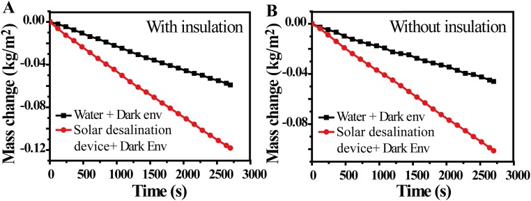
A cellulose-wrapped polystyrene foam (∼1.6 cm thick) was floated on the surface solution in a Dewar flask (Shanghai Glass Instrument Co.) or a beaker. A paper-based GO film (∼3.5 mm thick) was placed on the surface of cellulose-wrapped polystyrene foam. The samples were irradiated by a solar simulator (Newport 94043A, Class AAA) with an optical filter for the standard AM 1.5 G spectrum. The temperatures of the steam and surface water were recorded by two thermocouples (placed on the top surface of the GO film and on the water surface). The weight change was monitored by electronic analytical scale (FA 2004), real-time recorded by a desktop computer (with RS 232 serial ports), and then used to determine the evaporation rate and efficiency of solar steam generation. The evaporation rate of the dark field (Fig. S6) was subtracted from all of the measured evaporation rates under the irradiation. A commonly used double-slope solar still setup was used for steam condensation and water collection (44, 45). A clean glass plate was used as the roof to allow light to pass through. Under solar illumination, the steady steam will condense into water when it arrives at the cold chamber wall, and the condensed water automatically flows along the sidewall of the container into the condensation chamber.
Fig. S6.
The evaporation rate of water under dark conditions (A) using a Dewar flask and (B) using a beaker without extra thermal insulation.
Estimation of Heat Conduction Loss Through Bulk Water
Under a steady-state condition, the intrinsic heat conduction loss from the absorber to bulk water is calculated using the Fourier’s law
where q denotes the heat flux, k is the thermal conductivity of material, and ▿T is temperature gradient, determined by the temperature difference between surfaces of the absorber and water, and thickness of the absorber. The thermal conductivity of water (0.5 W/mK) is used for the estimation, as water is the dominant and intrinsic heating conduction path in most of the direct-contact designs (8, 10). (Table S1).
Heat Loss
The heat loss by the absorber consists of three losses: (i) radiation, (ii) convection, and (iii) conduction. The details of calculation are shown in Radiation.
Radiation.
It is assumed that the absorber has maximum emissivity of 1. For radiation loss to an ambient temperature of about 15 °C, the radiation loss was calculated by Stefan−Boltzmann
| [S1] |
where Φ denotes heat flux, ε is emissivity, A is surface area (4.9 cm2), σ is the Stefan−Boltzmann constant, T1 is the average temperature of absorber (there is uneven distribution of surface temperatures, and thus the average temperature was adopted in calculation), and T2 is an ambient temperature in our experiment. Therefore, based on Eq. S1, we can calculate that the radiation heat loss of the device with 2D water path accounts for ∼7% of all irradiation energy.
Convection.
The convection loss was calculated by Newton's law of cooling
| [S2] |
where Q denotes the heat, h is convection heat transfer coefficient, A is surface area (4.9 cm2), and ∆T is the difference between the absorber (as there is uneven distribution of surface temperature, the average temperature was adopted in calculation) and ambient temperature in our experiment. According to an early report in ref. 8, the convection heat transfer coefficient is about 5 W⋅m−2⋅K−1. Therefore, based on Eq. S2, we can calculate that the convection heat loss of the device with 2D water path accounts for ∼6% of all irradiation energy.
Conduction.
The device with 2D water path was put in a Dewar container under one-sun irradiation to calculate the conduction loss. The conduction loss was calculated based on
| [S3] |
where Q denotes the heat, C is the specific heat capacity of water (4.2 J/g per °C), t is the irradiation time, m is the water weights, and ∆T is the elevated water temperature within t seconds. Based on the experiment, t = 3,600 s, m = 42 g, and ∆T = 0.5 °C. Therefore, based on Eq. S3, we can calculate that the conduction heat loss of the device with 2D water path accounts for ∼5% of all of the energy. Please note that this calculation is different from the early one reported in ref. 8. In our study, the conduction loss refers to the heat from absorber to bulk water rather than the heat from system to ambient environment, as all of the heat loss to bulk water is considered as wasted when calculating the energy conversion efficiency in this work.
Comparison Between Our Solar Desalination with Conventional Desalination Strategies
Here, the most interesting feature of our approach is providing an efficient and effective solution for solar desalination, which is a promising solution to produce clean water directly out of solar energy without extra energy input, particularly urgent for developing countries and remote areas without basic infrastructures. More strikingly, the high efficiency is independent of water quantity (as shown in Fig. 5), without any extra optical or thermal supporting systems due to suppressed conduction loss. This is very different from most (if not all) of the common technologies such as reverse osmosis (RO) and distillation.
The technology of RO have widely used due to the fact that it requires relatively low investment and is easy to maintain. However, it uses high-cost electrical energy to keep the technology operation normal, which limits its wide use in some regions, especially in some countries and remote areas without basic infrastructures. One of the biggest advantages of our approach, compared with RO, is that it directly uses solar energy and has a minimized carbon footprint without extra energy input.
Solar desalination with low cost and a minimized carbon footprint can provide high-quality fresh water in many regions. However, the current technology of solar desalination is limited by the low efficiency and production rate due to the inefficient solar energy harvesting and large heat loss to the bulk saline water. One of the biggest advantages of our approach, compared with current commercially installed solar stills with efficiency of about 30 to 45% (10), is that it has high efficiency (∼80%) due to broadband and efficient solar absorption (AM 1.5 G weighted absorbance of ∼94% for 200 nm to 2,500 nm) and suppressed conduction heat loss from absorber to bulk saline water.
Acknowledgments
This work is jointly supported by the State Key Program for Basic Research of China (2015CB659300), National Natural Science Foundation of China (NSFC 11321063 and 11574143), Natural Science Foundation of Jiangsu Province (BK20150056), the Priority Academic Program Development of Jiangsu Higher Education Institutions, and the Fundamental Research Funds for the Central Universities.
Footnotes
The authors declare no conflict of interest.
This article is a PNAS Direct Submission. Y.C. is a Guest Editor invited by the Editorial Board.
This article contains supporting information online at www.pnas.org/lookup/suppl/doi:10.1073/pnas.1613031113/-/DCSupplemental.
References
- 1.Mekonnen MM, Hoekstra AY. Four billion people facing severe water scarcity. Sci Adv. 2016;2(2):e1500323. doi: 10.1126/sciadv.1500323. [DOI] [PMC free article] [PubMed] [Google Scholar]
- 2.Haddeland I, et al. Global water resources affected by human interventions and climate change. Proc Natl Acad Sci USA. 2014;111(9):3251–3256. doi: 10.1073/pnas.1222475110. [DOI] [PMC free article] [PubMed] [Google Scholar]
- 3.Sharon A, Reddy KS. A review of solar energy driven desalination technologies. Renew Sustain Energy Rev. 2015;41:1080–1118. [Google Scholar]
- 4.Shannon MA, et al. Science and technology for water purification in the coming decades. Nature. 2008;452(7185):301–310. doi: 10.1038/nature06599. [DOI] [PubMed] [Google Scholar]
- 5.Elimelech M, Phillip WA. The future of seawater desalination: Energy, technology, and the environment. Science. 2011;333(6043):712–717. doi: 10.1126/science.1200488. [DOI] [PubMed] [Google Scholar]
- 6.Neumann O, et al. Compact solar autoclave based on steam generation using broadband light-harvesting nanoparticles. Proc Natl Acad Sci USA. 2013;110(29):11677–11681. doi: 10.1073/pnas.1310131110. [DOI] [PMC free article] [PubMed] [Google Scholar]
- 7.Neumann O, et al. Solar vapor generation enabled by nanoparticles. ACS Nano. 2013;7(1):42–49. doi: 10.1021/nn304948h. [DOI] [PubMed] [Google Scholar]
- 8.Ghasemi H, et al. Solar steam generation by heat localization. Nat Commun. 2014;5:4449. doi: 10.1038/ncomms5449. [DOI] [PubMed] [Google Scholar]
- 9.Ito Y, et al. Multifunctional porous graphene for high-efficiency steam generation by heat localization. Adv Mater. 2015;27(29):4302–4307. doi: 10.1002/adma.201501832. [DOI] [PubMed] [Google Scholar]
- 10.Liu Y, et al. A bioinspired, reusable, paper-based system for high-performance large-scale evaporation. Adv Mater. 2015;27(17):2768–2774. doi: 10.1002/adma.201500135. [DOI] [PubMed] [Google Scholar]
- 11.Bae K, et al. Flexible thin-film black gold membranes with ultrabroadband plasmonic nanofocusing for efficient solar vapour generation. Nat Commun. 2015;6:10103. doi: 10.1038/ncomms10103. [DOI] [PMC free article] [PubMed] [Google Scholar]
- 12.Zhang L, Tang B, Wu J, Li R, Wang P. Hydrophobic light-to-heat conversion membranes with self-healing ability for interfacial solar heating. Adv Mater. 2015;27(33):4889–4894. doi: 10.1002/adma.201502362. [DOI] [PubMed] [Google Scholar]
- 13.Tian L, et al. Plasmonic biofoam: A versatile optically active material. Nano Lett. 2016;16(1):609–616. doi: 10.1021/acs.nanolett.5b04320. [DOI] [PubMed] [Google Scholar]
- 14.Zhou L, et al. Self-assembly of highly efficient, broadband plasmonic absorbers for solar steam generation. Sci Adv. 2016;2(4):e1501227. doi: 10.1126/sciadv.1501227. [DOI] [PMC free article] [PubMed] [Google Scholar]
- 15.Zhou L, et al. 3D self-assembly of aluminium nanoparticles for plasmon-enhanced solar desalination. Nat Photon. 2016;10(6):330–398. [Google Scholar]
- 16.Ni G, et al. Volumetric solar heating of nanofluids for direct vapor generation. Nano Energy. 2015;17:290–301. [Google Scholar]
- 17.Novoselov KS, et al. Electric field effect in atomically thin carbon films. Science. 2004;306(5696):666–669. doi: 10.1126/science.1102896. [DOI] [PubMed] [Google Scholar]
- 18.Singh V, et al. Graphene based materials: Past, present and future. Prog Mater Sci. 2011;56(8):1178–1271. [Google Scholar]
- 19.Park S, Ruoff RS. Chemical methods for the production of graphenes. Nat Nanotechnol. 2009;4(4):217–224. doi: 10.1038/nnano.2009.58. [DOI] [PubMed] [Google Scholar]
- 20.Zhu Y, et al. Graphene and graphene oxide: Synthesis, properties, and applications. Adv Mater. 2010;22(35):3906–3924. doi: 10.1002/adma.201001068. [DOI] [PubMed] [Google Scholar]
- 21.Chen D, Feng H, Li J. Graphene oxide: Preparation, functionalization, and electrochemical applications. Chem Rev. 2012;112(11):6027–6053. doi: 10.1021/cr300115g. [DOI] [PubMed] [Google Scholar]
- 22.Boukhvalov DW, Katsnelson MI, Son YW. Origin of anomalous water permeation through graphene oxide membrane. Nano Lett. 2013;13(8):3930–3935. doi: 10.1021/nl4020292. [DOI] [PubMed] [Google Scholar]
- 23.Nair RR, Wu HA, Jayaram PN, Grigorieva IV, Geim AK. Unimpeded permeation of water through helium-leak-tight graphene-based membranes. Science. 2012;335(6067):442–444. doi: 10.1126/science.1211694. [DOI] [PubMed] [Google Scholar]
- 24.Kim HW, et al. Selective gas transport through few-layered graphene and graphene oxide membranes. Science. 2013;342(6154):91–95. doi: 10.1126/science.1236098. [DOI] [PubMed] [Google Scholar]
- 25.Li H, et al. Ultrathin, molecular-sieving graphene oxide membranes for selective hydrogen separation. Science. 2013;342(6154):95–98. doi: 10.1126/science.1236686. [DOI] [PubMed] [Google Scholar]
- 26.Sun P, et al. Selective ion penetration of graphene oxide membranes. ACS Nano. 2013;7(1):428–437. doi: 10.1021/nn304471w. [DOI] [PubMed] [Google Scholar]
- 27.Joshi RK, et al. Precise and ultrafast molecular sieving through graphene oxide membranes. Science. 2014;343(6172):752–754. doi: 10.1126/science.1245711. [DOI] [PubMed] [Google Scholar]
- 28.Mi B. Graphene oxide membranes for ionic and molecular sieving. Science. 2014;343(6172):740–742. doi: 10.1126/science.1250247. [DOI] [PubMed] [Google Scholar]
- 29.Hu M, Mi B. Enabling graphene oxide nanosheets as water separation membranes. Environ Sci Technol. 2013;47(8):3715–3723. doi: 10.1021/es400571g. [DOI] [PubMed] [Google Scholar]
- 30.Sun P, et al. Ultrafast liquid water transport through graphene-based nanochannels measured by isotope labelling. Chem Commun (Camb) 2015;51(15):3251–3254. doi: 10.1039/c4cc10103k. [DOI] [PubMed] [Google Scholar]
- 31.Renteria JD, et al. Strongly anisotropic thermal conductivity of free-standing reduced graphene oxide films annealed at high temperature. Adv Funct Mater. 2015;25(29):4664–4672. [Google Scholar]
- 32.Tian L, et al. Graphene oxides dispersing and hosting graphene sheets for unique nanocomposite materials. ACS Nano. 2011;5(4):3052–3058. doi: 10.1021/nn200162z. [DOI] [PubMed] [Google Scholar]
- 33.Eda G, Fanchini G, Chhowalla M. Large-area ultrathin films of reduced graphene oxide as a transparent and flexible electronic material. Nat Nanotechnol. 2008;3(5):270–274. doi: 10.1038/nnano.2008.83. [DOI] [PubMed] [Google Scholar]
- 34.Shi L, et al. Fabrication of transparent, flexible conducing graphene thin films via soft transfer printing method. Appl Surf Sci. 2013;276:437–446. [Google Scholar]
- 35.Hummers WS, Offeman RE. Preparation of graphitic oxide. J Am Chem Soc. 1958;80(6):1339. [Google Scholar]
- 36.Boukhvalov DW, Katsnelson MI. Modeling of graphite oxide. J Am Chem Soc. 2008;130(32):10697–10701. doi: 10.1021/ja8021686. [DOI] [PubMed] [Google Scholar]
- 37.Xu Y, et al. Highly conductive chemically converted graphene prepared from mildly oxidized graphene oxide. J Mater Chem. 2011;21:7376–7380. [Google Scholar]
- 38.Pham VH, et al. Fast and simple fabrication of a large transparent chemically-converted graphene film by spray-coating. Carbon. 2010;48(7):1945–1951. [Google Scholar]
- 39.Li X, Zhang D, Yang C, Shang Y. Direct and efficient preparation of graphene transparent conductive films on flexible polycarbonate substrate by spray-coating. J Nanosci Nanotechnol. 2015;15(12):9500–9508. doi: 10.1166/jnn.2015.10482. [DOI] [PubMed] [Google Scholar]
- 40.Yamaguchi H, Eda G, Mattevi C, Kim H, Chhowalla M. Highly uniform 300 mm wafer-scale deposition of single and multilayered chemically derived graphene thin films. ACS Nano. 2010;4(1):524–528. doi: 10.1021/nn901496p. [DOI] [PubMed] [Google Scholar]
- 41.Xu Y, et al. Solution processable holey graphene oxide and its derived macrostructures for high-performance supercapacitors. Nano Lett. 2015;15(7):4605–4610. doi: 10.1021/acs.nanolett.5b01212. [DOI] [PubMed] [Google Scholar]
- 42.Adediji A, Ajibade LT. Quality of well water in Ede Area, southwestern Nigeria. J Hum Ecol. 2005;17(3):223–228. [Google Scholar]
- 43.Iqbal H, et al. Physico-chemical analysis of drinking water in district Kohat, Khyber Pakhtunkhwa, Pakistan. Int J Basic Med Sci Pharm. 2013;3(2):37–41. [Google Scholar]
- 44.Rajaseenivasan T, et al. A review of different methods to enhance the productivity of the multi-effect solar still. Renew Sustain Energy Rev. 2013;17:248–259. [Google Scholar]
- 45.Xiong JY, et al. Experimental and numerical study on a new multi-effect solar still with enhanced condensation surface. Energy Convers Manage. 2013;73:176–185. [Google Scholar]


