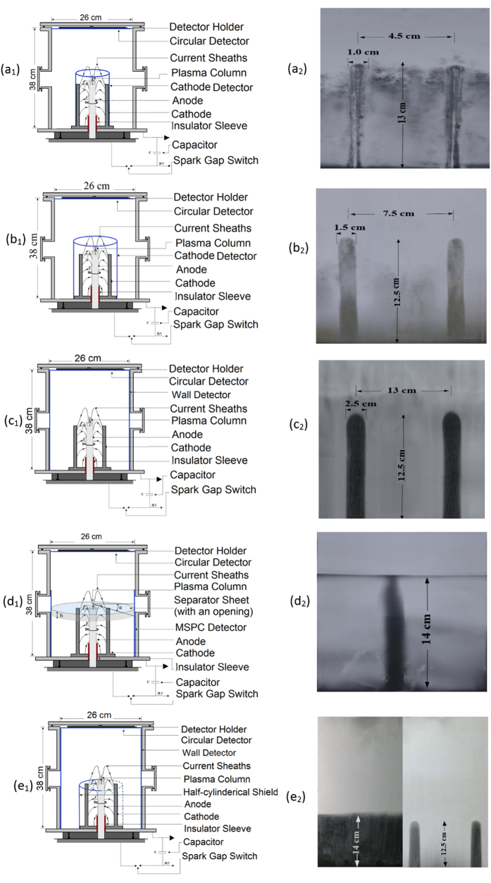
Figure 5.
(a–e) Five MSPC detector set-ups and “ICS” images on detectors. (a1,2) A rectangular cathode MPC detector attached to the cathodes (a1) and images of two “ICSs” on it (a2); (b1,2) A rectangular cathode MSPC detector installed 3 cm away from the cathodes (b1) and image of two “ICSs” on it (b2); (c1,2) A rectangular MSPC detector placed on the PFD wall (c1) and images of two “ICSs” on it (c2); (d1,2) A circular sheet, 1 mm thick, with 5 cm circular opening in the middle which can separate the PFD volume into two upper and lower spaces (d1) and an image of one “ICS” formed on it (d2); and (e1,2) A rectangular PC sheet attached around 3 cathodes to shield ions to reach a wall detector while the other 3 cathodes were allowed to emit ions to reach another wall MSPC detector (e1), and two separate images; one image on the wall detector with the lower part shielded from ions emitted from the “anode cathodes array” (left) and one image of “ICS” on a wall detector with no shield in front of it (right) (e2).

