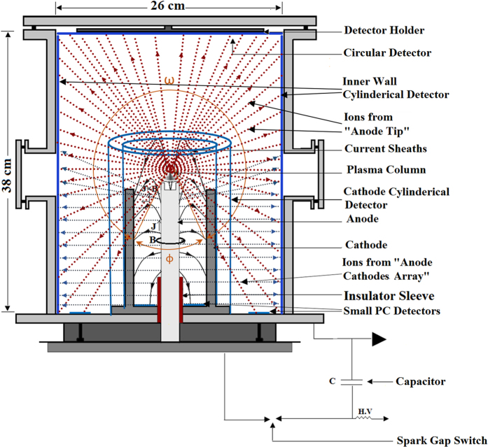
Figure 6. Schematic diagram of PFD space with PC detector arrangements.
Schematic diagram of the inner space of the PFD showing a circular MSPC detector attached to top cylinder base facing the “anode top”; a rectangular MSPC detector laid on the inner wall; smaller rectangular MSPC detectors (one wrapped around and attached to the cathodes and another at a distance away from the cathodes, but exposed one at a time); as well as small PC detectors laid on the ground cylinder base (some on the area between the anode and cathodes as well as some on the area between the cathodes and the wall). It should be noted that each of the cathode or wall detectors was independently exposed either with a circular detector and/or small detectors on the ground PFD base.

