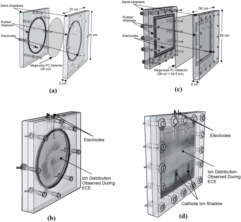
Figure 7.
(a–d) Schematic diagrams of two designs of MS-ECE chambers. MS-ECE chambers; (a) a circular MS-ECE chamber with a circular MSPC detector in the middle when the chamber components and the detector are not assembled and (b) when they have been assembled showing also a helium ion angular distribution image on the circular MSPC detector as observed during ECE; as well as (c) a rectangular MSEC chamber with a rectangular MSPC detector in the middle when chamber components and the detector are not assembled and (d) when they have been assembled showing a helium ion distribution image as observed during the ECE processing. The images of ion emission angular distributions on both MSPC detectors in particular those of the “ICSs” are distinctly observable by the unaided eyes during and in particular after the end of an optimized ECE processing.

