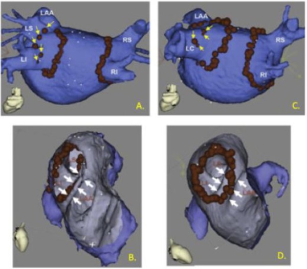
Figure 1. Anatomy tailored ablation by merging 3D angiogram information with electroanatomic mapping catheter guidance. Red dots indicate locations were ablation energy was delivered. A) A procedure where pulmonary vein isolation was achieved by circumferential ablation around the right and left pair of PVs followed by segmental ablation, encroaching closer to the veins, marked by yellow arrows. B) Ablation was guided to the PV side of a narrow left atrial appendage ridge, marked by white arrows. C) A patient with a left common PV and D) ablation could be directed onto a wider left atrial appendage ridge. (Adapted from Dong, et.al. Circulation 2006).

