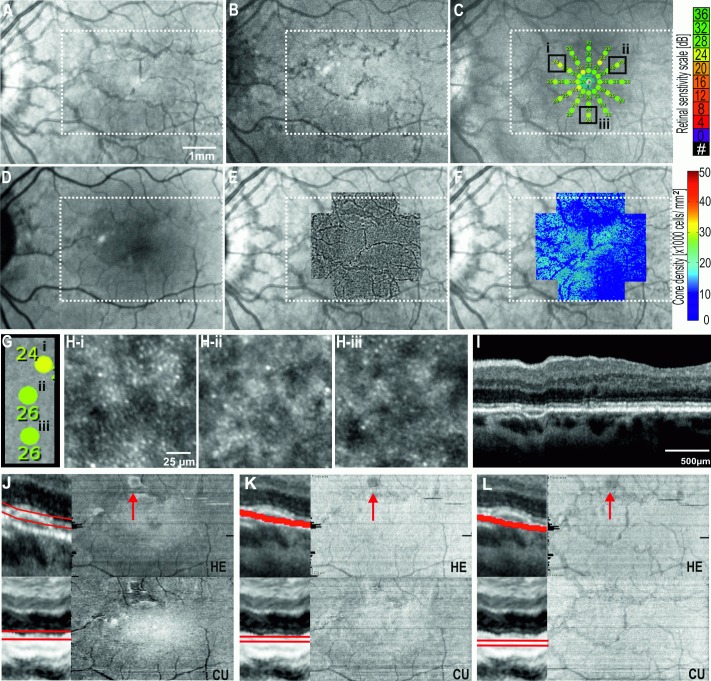
Fig 4. Multimodal imaging showing the left eye of Case 1: angioid streaks secondary to pseudoxanthoma elasticum.
Near-infrared reflectance NIR (A), infrared autofluorescence IRAF (B), microperimetry (C), blue-light autofluorescence BAF (D), and adaptive optics flood illumination ophthalmoscopy AO-FIO cone montage and density maps overlaid on NIR image (E, F) of the central 15° × 10° showing the angioid streaks as irregular linear hypo-reflective lesions. The occasional streaks showing hypo-autofluorescence, relative scotoma in regions unaffected by angioid streaks and cone tip reflexes within the region of angioid streaks. Microperimetry overlaid on cone tip reflex montage (G) showed reduced cone densities compared with normative values, both in regions with reduced (H:I) and normal sensitivity (H:II-III). B-scans flattened to the base of retinal pigment epithelium RPE (I) are used for generating en face OCT images of the ellipsoid zone (J), apical portion of the RPE (K) and basal portion of the RPE (L). Inaccuracy in automated segmentation of the basal RPE by HE resulted in artefact in the ellipsoid zone and RPE en face OCT images (red arrow in K, L and M). The linear pattern of angioid streaks were only visible in the en face OCT image derived from the basal portion of the RPE (L). HE, Heidelberg Eye Explorer software (Heidelberg Engineering); CU, Custom-built software using graph-search theory algorithm. White dotted rectangle corresponds to region for which en face OCT images are generated.

