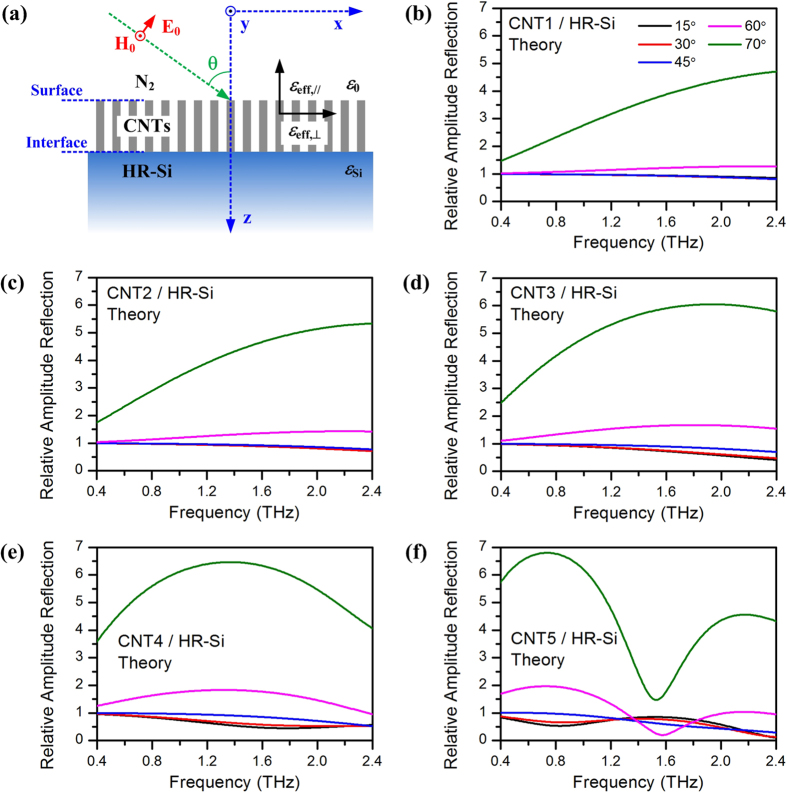
Figure 6.
(a) Schematic diagram of p-polarized THz wave reflected from a CNT array, which is equivalent to an anisotropic layer with effective dielectric constants of εeff,⊥ and εeff,∥ for incident THz electric fields perpendicular and parallel to the CNT axial (z-axial). (b–f) Theoretically calculated relative amplitude reflection of CNT1, CNT2, CNT3, CNT4 and CNT5 compared with HR-Si, respectively. Reflection with elevated incident angles 15°, 30°, 45°, 60° and 70°, is shown as lines with different colors.

