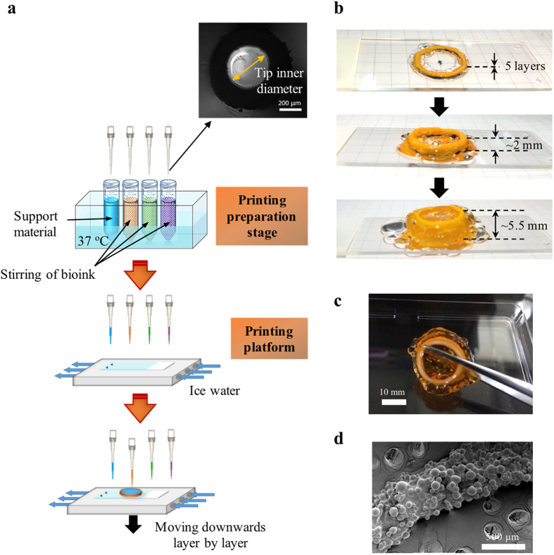
Figure 4. Schematic of an automated bioprinting system and the 3D-printed prototype.
(a) The system should consist of four major units: (i) a 3-axis robotic controlled dispensing system using micropipette tips, (ii) a printing preparation stage with boxes of new micropipettes and bioinks under stirring and temperature control (37 °C), (iii) an ice-water-chilled printing platform, and (iv) a closed chamber with humidifier, UV lamp, and trash container. Before printing, the chamber can be sterilized with UV lamp. Bioinks can be prepared prior to loading into the printing preparation stage. Printing is conducted on the chilled platform where the hydrogel will glue the microspheres into designed shapes layer by layer. Tips will be removed into the trash container after layers of printing and new tips will be fetched onto the dispensing system before drawing the bioinks for subsequent printing. Inset shows the OM image of the micropipette tip. (b,c) Pictures of 3D-printed tubular construct with gelatin (transparent) as support. Constructs were printed on superfrost plus microscope slides with a dimension of 25 mm × 75 mm. (d) SEM image of printed construct showing tightly packed microspheres.

