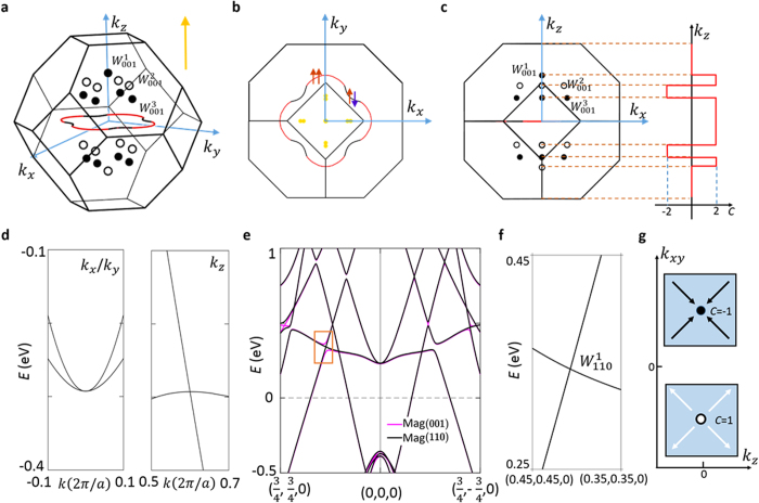
Figure 4. Weyl nodes and nodal-lines in Co2TiX in the presence of spin-orbit coupling.
(a) Band crossings in the first BZ. There are one nodal line on kz = 0 plane and three types of Weyl nodes (shown by the dots) in the first BZ. The white and black colors denote the chiral charge of the Weyl nodes. (b) The projection of the band crossings on the (001) top surface. The projected Weyl nodes are shown by the yellow dots, all of which have a projected chiral charge of 0 as two Weyl nodes of opposite chiralities are projected onto the same point on the (001) surface. The nodal line in panels (a,b) is shown by the solid lines which are in two colors (red and black). The red segments denote the band crossings formed by two bands of the same (majority) spin whereas the black ones are formed by bands of opposite spins. (c) The projection of the band crossings on the (010) side surface (left panel) and the schematic of the Chern number as a function of
kz (right panel). (d) The energy dispersions along kx/ky (left panel) and kz (right panel) directions of  Weyl cone. The quadratic touching of two bands along kx/ky direction proves that the chiral charge of the Weyl cone is ±2. (e) A comparison of the band structures of Co2TiX with a (001) or (110) magnetization direction. The number and momentum space locations of the Weyl nodes critically depend on the magnetization directions. (f) The zoom-in view of the area indicated by the orange box in panel (e). Unlike the case in the (001) magnetization, the band crossing remains intact with the (110) magnetization, and therefore becomes a Weyl node, the
  . (g) A sketch depicting the Berry curvatures of
the Weyl nodes in the kz − kxy plane. The chiral charge of the Weyl node is denoted.

