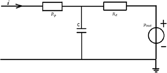
Figure 9. The schematic illustration of the Windkessel model.

The parameters were defined as follows: Rp represents the proximal resistance, Rd represents the distal resistance, C represents the compliance of the artery, pout represents the pressure in the realistic terminal, and i represents the flow rate at the boundary outflow.
