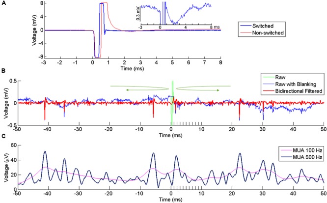
FIGURE 2.

Artifact reduction and extraction of neural signal. (A) Artifact at a recording channel 400 μm away from the stimulating channel with (blue) our without (red) switching between stimulating and recording modes. Time 0 indicates the onset of stimulation. The stimulation lasts for ∼ 0.5 ms, resulting in the first negative phase of the artifact. In the non-switched mode, the artifact lasts for more than 0.5 ms after the offset of stimulation due to saturation of the amplifier. The long tail of the artifact is suppressed in the swicthed-mode, allowing fast recovery of neural activity after the stimulation offset. The inset plot shows the response in the switched mode at higher amplitude resolution. (B) Superimposed broad-band signal with the stimulation artifact (green), broad-band signal after artifact replacement (blue) and its high-pass filtered version (red) following bidirectional filtering separately applied to the pre-stimulus and post-stimulus signal, in the direction indicated by the green arrows. A clear spike is visible right after stimulus offset. (C) MUA computed from the signal in (B), using two different cutoff frequencies (100 and 500 Hz).
