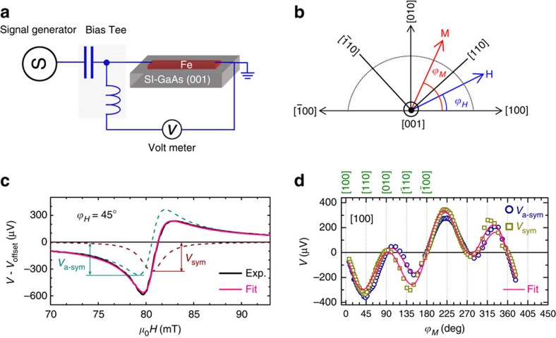
Figure 2. Spin-orbit ferromagnetic resonance measurements.
(a) Depiction of sample structure and experimental set-up. A microwave current passes through the Bias Tee and to the sample to drive the magnetization dynamics in the Fe film. A rectified dc voltage is detected across the Fe stripe. (b) Definition of magnetic-field angle ϕH and magnetization angle ϕM. (c) Typical spectrum of the dc voltage V obtained at a magnetic-field angle of ϕH=45°, microwaves frequency of 12 GHz, and temperature of 300 K, where the offset voltage Voffset is subtracted. (d) Dependence of Va-sym and Vsym on the magnetization angle ϕM for a [100]-orientated device. The solid lines are fits to equation (1).

