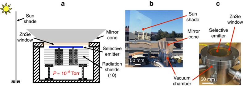
Figure 2. Experimental concept.
(a) Schematic of the experimental set-up. The key feature is to minimize parasitic heat losses of convection and air conduction using a vacuum system. Radiation shields and long-hollow ceramic pegs are exploited to further reduce the radiation and conduction losses through the backside of the selective emitter. The shinny sun-shade and mirror-cone are used to minimize solar irradiance. ZnSe is selected for its transparency in the mid-infrared wavelength range (red line in Fig. 3b). (b) In situ experimental set-up. (c) Details of the vacuum chamber, including the selective emitter and the ZnSe window.

