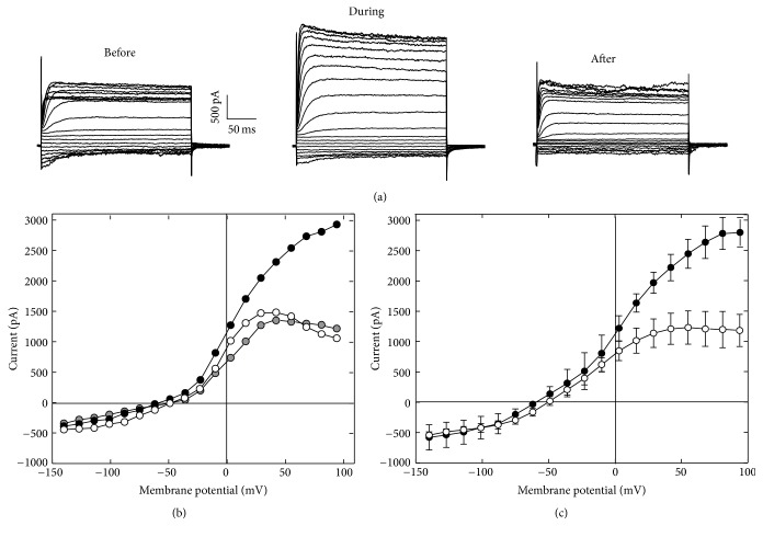
Figure 3.
Urethane-induced membrane current changes. (a) Example of the membrane current waveforms recorded from a solitary OHC before, during, and after 100 mM urethane application. The cell was held at −70 mV, and voltage commands varied from −140 to +94 mV in 13 mV steps. (b) The I-V curves derived from the steady-state responses shown in (a). The open, black, and gray filled circles represent the responses before, during, and after urethane application, respectively. (c) Plot of the average (±SD) I-V curves recorded from OHCs (n = 11) before (open circles) and during (filled circles) urethane application.

