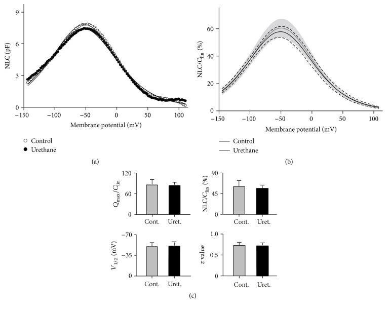
Figure 5.
The effects of urethane on the NLC measured from OHCs. (a) The NLC obtained from a representative OHC before (control, open circles) and during (urethane, filled circles) 100 mM urethane application. The capacitance-voltage responses were fitted to the Boltzmann function (shown as the gray and black lines). C lin was subtracted from the NLC. pF, picofarads. (b) Pooled data of the NLCs recorded from 10 OHCs. The NLCs were normalized to the corresponding C lin, and the curves were plotted as the mean NLC ± SD. The SD around the mean is indicated by the shaded region for the control and by dashed lines for urethane treatment. (c) Four parameters derived from the curve fit to the Boltzmann function. The data are expressed as the means and the SDs; N = 10. No significant difference was detected between the cases before and during urethane application (Student's t-test, p > 0.05).

