
Figure 1.
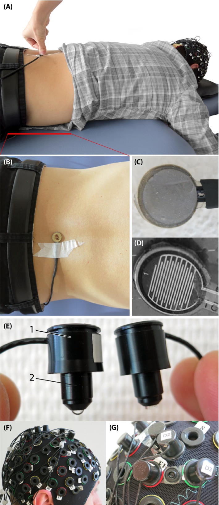
Experimental setup. (A) Subject lying in prone position on a massage bench, while the examinant is applying a posterior‐to‐anterior pressure on the force sensor attached on third lumbar spinous process (L3). (B) Pressure sensor from top view, attached on the L3. (C) The force sensor from the bottom (this side is placed on the skin), (D) The inside of the force sensor. (E) The optodes, left with 1) the enclosure of the optic fibers and 2) the tip of the light emission diode (LED) source and right of the detector. (F) Probe array on the subjects head, (G) Fixation of a source and detector distance by using so‐called distance holders