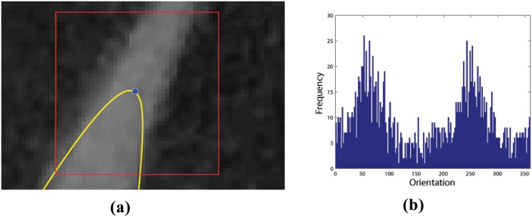
Fig 3. Determining the local orientation field.
The figure illustrates the basis for determining the direction of “particle” evolution. (a) A small 40 × 40 pixel window (red) is created with the control point (blue) of the initial contour (yellow) at its geometric centre. (b) A frequency histogram of orientation field angles for every pixel inside the window. As the orientation field of background pixels is for the most part relatively random, the two peaks corresponding to the two leaf edges become prominent in this histogram. These are employed to give direction to the “particle” evolution process.

