. 2016 Nov 9;9(12):3783–3793. doi: 10.1039/c6ee02598f

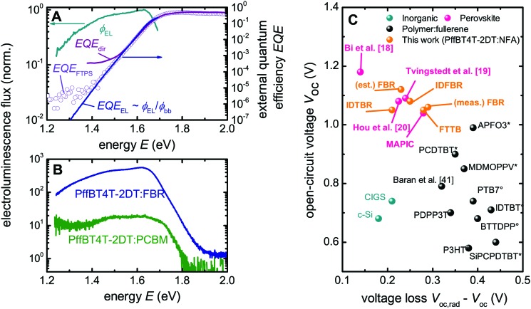
Fig. 5. Calculation of the voltage loss PffBT4T-2DT:FBR and comparison with other solar cells. (A) The EQE (solid line) determined from the EL, the directly measured quantum efficiency (purple line) and FTPS (open circles) used to determine the V oc,rad (1.35 V) of the PffBT4t-2DT:FBR device and the voltage loss due to non-radiative recombination (ΔV oc). (B) Electroluminescence emission spectra comparison of PffBT4t-2DT:PCBM and PffBT4t-2DT:FBR cells at a given current density (150 mA cm–2) using Si-detector. EL emission spectrum of PffBT4t-2DT:IDTBR using InGaAs detector can be found in ESI Fig. 6. (C) Comparison of the relation between V oc and ΔV oc,nr for different photovoltaic technologies including this work with non-fullerene acceptors. * Denotes the devices made with PC60BM and ° is for the devices made with PC70BM, using the data from ref. 17. The estimated voltage loss for FBR (est. FBR) is calculated by assuming the best FBR devices have similar V oc,rad as average FBR devices. For further information about the different devices, see Table S3 (ESI).

Fig. 5