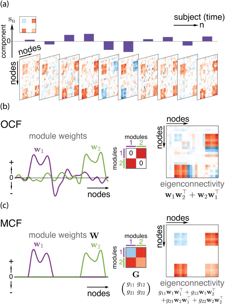
Fig 1. Illustration of OCF and MCF.
(a) Single component sn characterizes variability of connectivity xij with a block-structured eigenconnectivity matrix (top left). Here we illustrate a general situation such that diagonal elements xii may also vary. (b) OCF’s parametric eigenconnectivity matrix. Two orthogonal weight vectors define two modules, whose symmetrized outer product gives an eigenconnectivity matrix (red: positive, blue: negative). Intra-module eigenconnectivity is assumed to be zero (as illustrated in the middle), but spurious patterns may appear (diagonal parts of eigenconnectivity matrix). (c) Similar illustration for MCF, which explicitly imposes disjointness and nonnegativity on module weights W = (w1, w2). 2 × 2 real matrix G fully represents both intra- and inter-module eigenconnectivities; WGW⊤ (i.e., the above four terms) gives a node-level eigenconnectivity matrix.

