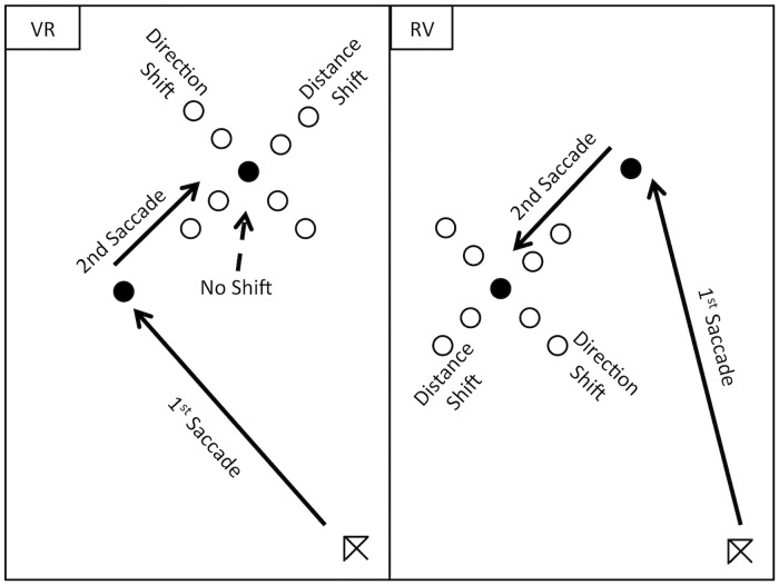
Fig 2. Shows schematic of the potential position shifts applied to the second target location (either no shift; a shift in distance or direction from 1st target location) made during first saccade execution.
The potential position shifts for the second (Reflexive) target (including no shift) are shown on the left and the potential shift locations for the second (Voluntary) target are shown on the right (note the targets were black spots and remained so when their location was shifted. The shifted second target locations are depicted here as unfilled circles to allow their positions to be more easily discerned by the reader). Distance shifts were toward or away from the first target location (0.75 or 1.5 degrees of visual angle). Direction shifts were clockwise and counter clockwise to the first target location (10 and 20 angular degree shifts).

