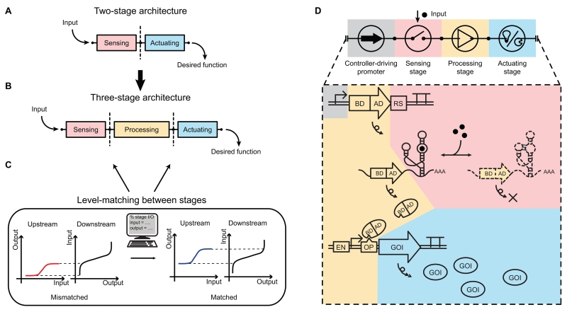
Figure 1. Three-stage controller architecture with model-facilitated level matching and the design of an RNA-based gene activation controller.
(A) Two-stage controller architecture with a sensing stage (pink) and actuating stage (blue).
(B) Three-stage controller architecture with a processing stage (yellow) between sensing and actuating stages.
(C) Level matching between stages. Mismatched levels (left, red and black curves) between stages versus computationally matched levels between stages (right, blue and black curves).
(D) Circuit diagram (top) and biological implementation (bottom) of a gene activation controller. Pink: sensor, small molecule-responsive RNA switches. Yellow: processor, transcription-based amplifiers. Blue: actuator, gene products. Biological elements: DNA (double lines), RNA (single lines), and proteins (ovals).
Abbreviations: AD: activation domain; BD: DNA-binding domain; RS: RNA switch; TA: transcription-based amplifier; EN: epigenetic enhancer; OP: operator site; GOI: gene-of-interest.

