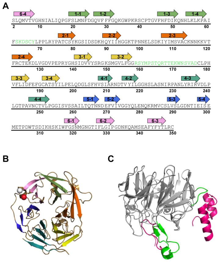
Figure 3. Core RAG2 topology and interface with RAG1.
(A) Murine core RAG2 sequence. Arrows are shown above residues that constitute the beta strands in the beta-propeller structure. The first number in each arrow corresponds to the blade number (1 to 6). The second number refers to the strand (1 to 4) in each blade, where strand 1 and 4 are at the interior and exterior sides of the blade, respectively, according to the orientation of the structure shown in panel B. Residues in green are positioned at the interface with RAG1 in the crystal structure of RAG12RAG22. (B) Ribbon diagram of murine core RAG2 (from PDB ID: 4WWX). The N- and C-termini are shown as white and red spheres, respectively. Each propeller blade is color coded according to the arrows in panel A, where blades 1 to 6 are in light green, orange, yellow, light blue, dark blue, and pink, respectively. (C) The core RAG2 structure rotated by 90° relative to panel B. Residues in the interface with RAG1 are shown in green, and correspond to the residues in green in panel A. The murine core RAG1 loops (residues 537-553 and 750-782) that form the majority of the interface with core RAG2 are shown as magenta ribbons.

