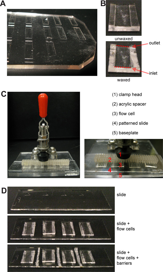
Figure 4. Preparation of PDMS flow cells.
(A) PDMS flow cells are cut out individually from a mold, shown here. (B) Prior to placement on the slide, flow cells are flipped upside-down and microcrystalline wax is applied to the underside of the side walls. (C) A 25×75 mm slide (top) can fit four flow cells (middle), each flow cell positioned over a pattern of DNA spots. Wax barriers are drawn between flow cells (bottom), preventing cross-contamination. (D) The slide and flow cells are secured within a mounted toggle clamp.

