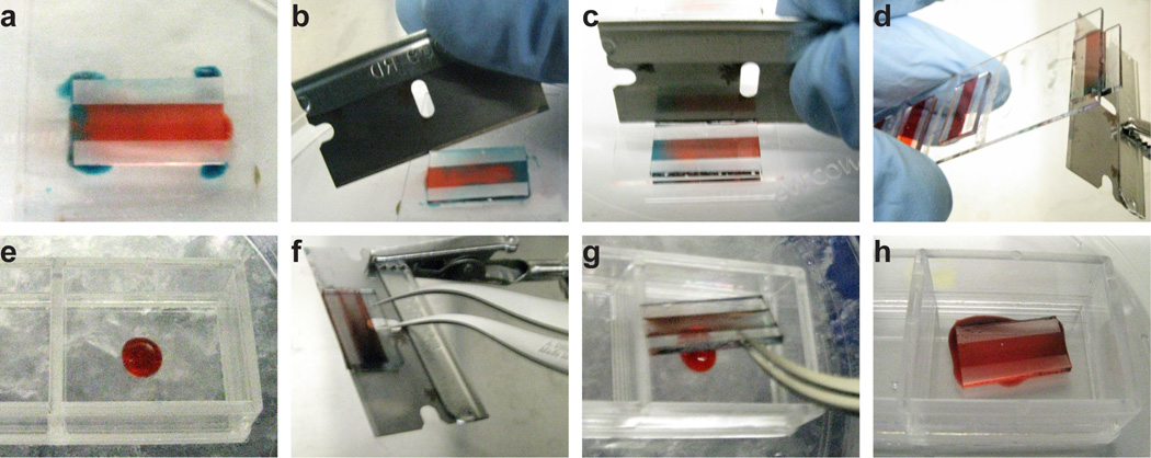
Figure 7. 3D transfer manipulations.
(A) 6 µL of media, here dyed blue, is dispersed around the corners of a flow cell. (B) A razor blade is inserted under the side walls of the flow cell, allowing the media to infiltrate between the PDMS and the glass slide. (C) The razor blade is brought perpendicular to the face of the slide and pushes the flow cell towards the edge of the slide. (D) The slide is inverted, and the razor blade is brought in at an angle such that, as the razor blade pushes the flow cell off the slide, the flow cell falls onto the razor blade. (E) The underlay gel, which is 30 µL of cold Matrigel, is deposited in the center of a two-well chambered coverglass. (F) Self-closing tweezers are used to grip the flow cell on the razor blade. Note the position of the razor blade's hole relative to the flow cell. (G) The flow cell is brought into position above the underlay gel with the tweezers. The flow cell and tweezers are angled such that opening the tweezers drops the flow cell onto the underlay. (H) The flow cell is deposited onto the underlay, spreading out the gel droplet.

