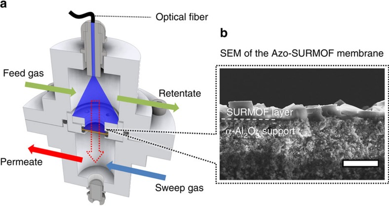
Figure 4. Membrane separation setup.
(a) Sketch of the setup for the photoswitchable membrane permeation experiments. The feed-retentate gas flow is above the membrane, while the sweep-permeate gas flow is below the membrane. A fiber-coupled LED is used for in situ irradiation of the SURMOF-covered top-side of the alumina membrane. (b) SEM cross-section image of the SURMOF membrane on the mesoporous α-alumina support. A dense SURMOF layer with a thickness of roughly 2 μm is observed. The length of the white scale bar is 5 μm.

