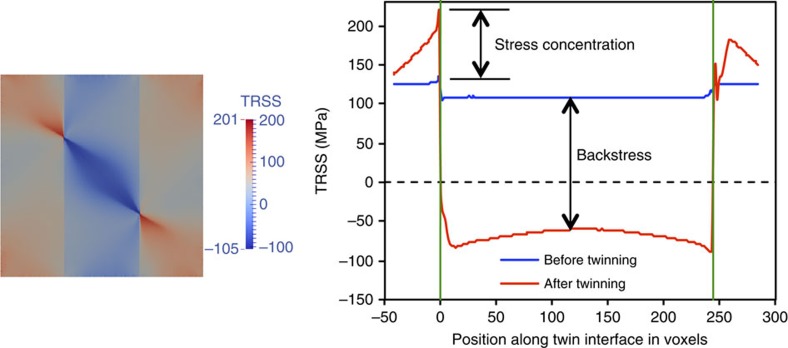
Figure 5. Distribution of twinning shear-induced TRSS field.
TRSS field after twinning and the TRSS profile along twin boundary before and after twinning in Zr for the neighbour orientation (0°, 30°, 0°). The stress concentration ahead of twin tip is marked. The twin tip/grain boundary junctions are marked by two vertical green lines.

