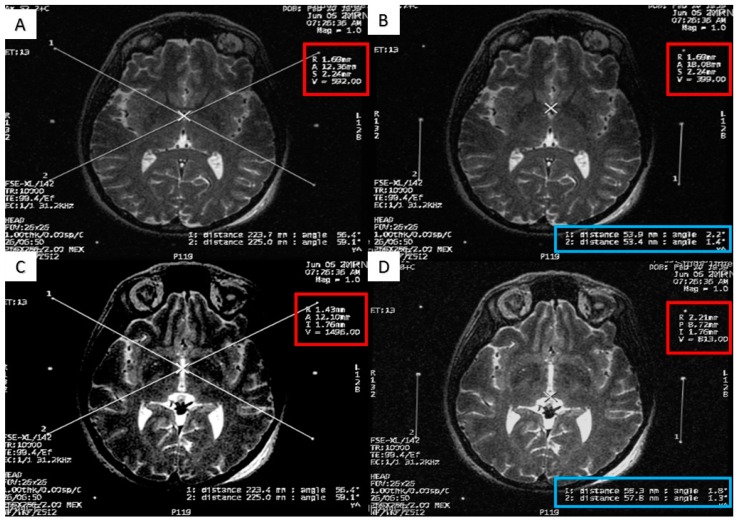
Figure 4.
Calculating the anterior commissure (AC) and posterior commissure (PC) coordinates using the magnetic resonance console. (A) Two diagonal lines intersecting at the center of the frame at the AC level with the magnetic resonance imaging (MRI) coordinates of the center of the frame shown inside the red square; (B) a crosshair at the posterior margin of the AC, with the MRI coordinates of the AC shown inside the red square. Two lines are drawn between the middle and the lower fiducials on both sides of the frame and their lengths (in the blue rectangle) are used to calculate the Z coordinate of the AC. (C) Two diagonal lines intersecting at the center of the frame at the PC level with the MRI coordinates of the center of the frame shown inside the red square; (D) a crosshair at the anterior margin of the PC, with the MRI coordinates of the PC shown inside the red square. Two lines are drawn between the middle and the lower fiducials on both sides of the frame and their lengths (in the blue rectangle) are used to calculate the Z coordinates of the PC.

