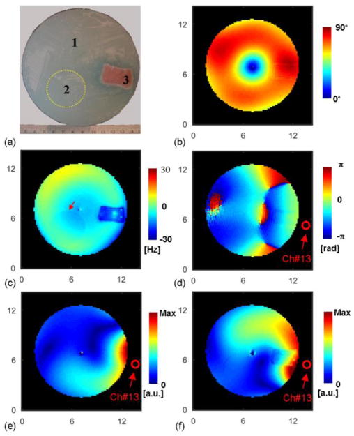
Fig. 4.
Experimental condition. (a): Photograph of a cross section of the phantom showing pork muscle and a small spherical compartment of gel as indicated by the yellow dash circle. (b): Measured flip angle distribution in CP2+ B1 shimming configuration. (c): Measured ΔB0 field map in Hz. Red arrow indicates the boundary of the small gel compartment. (d): Measured image phase distribution using channel #13 for both transmission and reception. (e): Measured magnitude of transmit B1 field of channel #13. (f): Measured proton density-weighted magnitude of receive B1 field of channel #13. The axis unit is cm.

