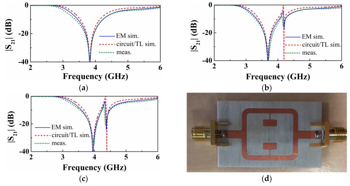
Figure 3.
Insertion losses for the structure of Figure 2. (a) For the symmetric structure with both SIRs identical to the upper SIR of Figure 2, with l1,u = l1,l = 2.6 mm; (b) for the asymmetric structure with lower SIR having bigger capacitance (increasing 0.494 mm or Δl1,l = 0.19l1,l) and (c) for the asymmetric structure with lower SIR having smaller capacitance (decreasing 0.494 mm or Δl1,l = – 0.19l1,l). For all three cases, the dimensions of the others are the same: W1,u = W1,l = 5.5 mm, W2,u = W2,l = 0.25 mm, l2,u = l2,l = 2.6 mm, W0 = 1.84 mm, W3 = 3.1 mm, θ1 = 0.8π, θ2 = 0.5π. The reactive parameters are: (a), Lu = Ll = 2.59 nH, Cu = Cl = 0.67 pF; for (b), Cl = 0.77 pF and for (c), Cl = 0.56 pF, with the other parameters the same as in (a). The photograph of the fabricated structure corresponding to the symmetric case is depicted in (d).

