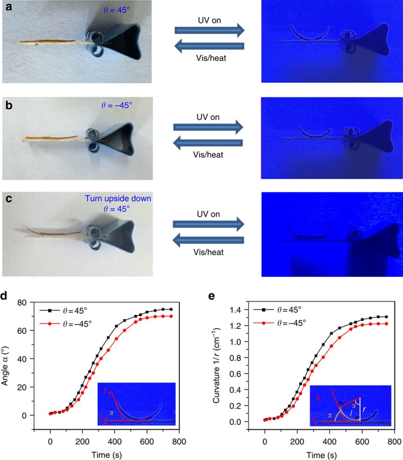
Figure 3. Ultraviolet-induced bending behaviour of two bilayer LCE ribbons.
The bilayer LCE ribbon with a (a) 45° or (b) −45° angle between the top and bottom layer was irradiated under 365 nm ultraviolet light. (c) The bilayer ribbon (θ=45°) was turned upside down and irradiated under 365 nm ultraviolet light. Supplementary Movies 1–3 show these scenarios in motion. (d) The included angle α vs ultraviolet illumination time diagram of the bilayer LCE ribbons. The error bars indicate the standard deviation of the measured angles. (e) Curvature (1/r) of the bilayer LCE ribbons as a function of ultraviolet illumination time. The error bars indicate the standard deviation of the bending curvature calculated from the included angle data.

