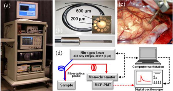
Fig. 1.

(a) Photograph of the TRFS system. (b) Photograph of the fiber optic probe used in clinical setting: inset on the right depicts the fiber front end, and the inset below depicts the tip of the fiber probe. (c) Distal end of the fiber probe positioned on brain cortex; the picture depicts the spacer with two slits allowing for maintaining a fixed distance from the tissue and application of a suction tube to provide a clear field. (d) Schematic of the TRFS system. Adapted from [29].
