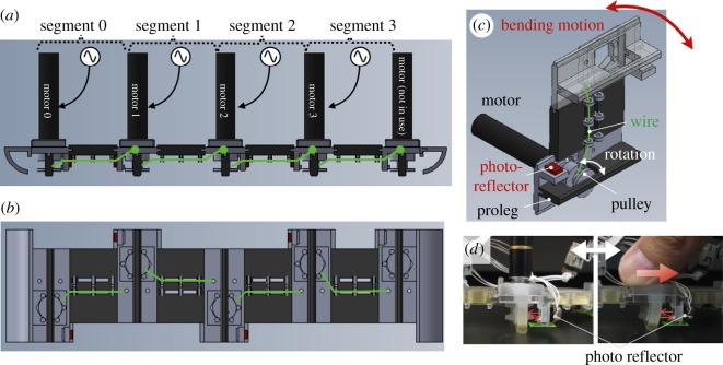
Figure 6.
(a) Side view and (b) bottom view of CAD image of the entire robot composed of four segments. (c) CAD image of one segment. The black parts are three-dimensionally printed with rubber-like materials (except for the motors) whereas the grey parts are three-dimensionally printed with hard and rigid materials. The green lines indicate wires that are wound and unwound by the motors in the segment. (d) Photos describe how to detect the deformation of the proleg with the photoreflector.

