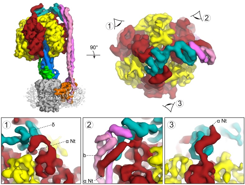
Figure 4. Subunit δ and peripheral stalk attachments to the α subunits.
Top panel; left, the segmented cryoEM map viewed from the side and right, viewed from above with the orientation of views 1, 2 and 3 depicted. Bottom panel; detailed views of the three attachment points labeled 1, 2 and 3, with δ in teal, b in pink and magenta and α in red.

