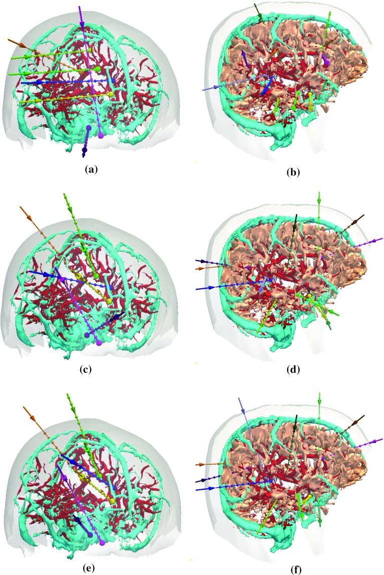
Fig. 7.
Two plans calculated by: a, b MP; c, d STP; and e, f MTP. Each plan shows the skull template (semi-transparent white), critical structures (arteries in red, veins in cyan, and sulci in peach). and trajectories [different coloured entry (arrow) and target (sphere)]. In a, c, and e sulci are not shown, so the electrode configuration can be appreciated

