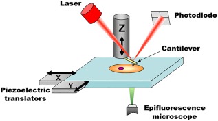
Figure 1.

Main elements of a bio‐AFM setup. The tip interacts with the probed sample and attractive/repulsive forces cause the cantilever to bend. Bending is monitored by shining a laser light onto the gold‐coated backside of the cantilever and measuring the position of its reflected light using a four quadrant photodiode. A set of three piezoelectric positioners allows nanometer‐scale movement of the tip with respect to the sample. The stage is typically moved in the x‐y axis, while the cantilever is moved on the z axis. Other configurations are also commercially available, for example, x‐y‐z piezoelectrics moving only the cantilever or only the sample. In commercial systems, the AFM stage is fitted directly onto the body of the epifluorescence microscope (replacing its own stage), to allow seamless integration and an unobstructed optical path for imaging.
