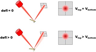
Figure 2.

Optical‐based detection of cantilever deflection. (Top) When the cantilever is resting undisturbed, the photodiode is manually placed in such a way that half of the laser spot reaches the top quadrants, and the other half the bottom quadrants. (Bottom) When the cantilever deflects, the laser spot reaches the photodiode at a slightly different location, causing the output voltages for the top and bottom quadrants to be different.
