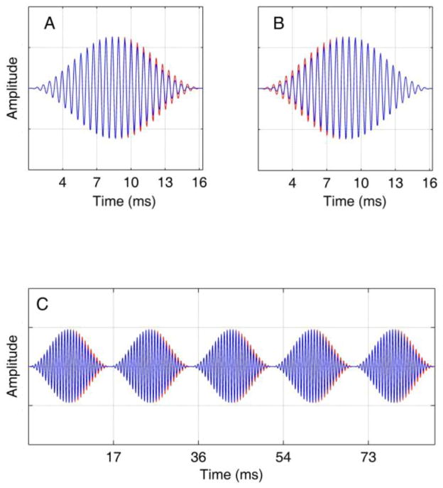
Figure 2.
Stimuli used in experiment 1 contained an interaural delay either in the negative (A) or positive (B) modulation slope, and were generated from concatenation of individual modulation cycles whose envelope peaks were extended by the desired interaural delay (C). The blue waveforms are plotted on top of the red waveforms, with the blue representing the stimulus delivered to one ear, and the red the stimulus to the other ear. The stimulus shown in panel C is a 4-kHz carrier modulated at 150 Hz with a 250-μs interaural delay applied to the negative slope.

