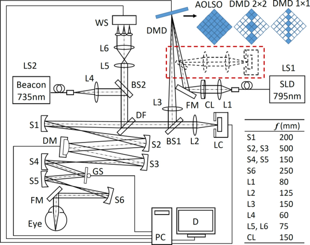
Fig. 1.
The AOPCSO system. SLD: superluminescent diode. DMD: digital micromirror device. LS1, LS2: Light sources. CL: Cylindrical lens. DF: Dichroic filter. L1–L6: Lenses. BS1, BS2: Beam splitter. S1–S5: Spherical mirrors. GS: Galvanometric scanner. FM: Flat mirrors. WS: Wavefront sensor. DM: Deformable mirror. LC: Line camera. PC: Computer. D: Display. Dash lines indicate the configuration in which the DMD is placed in both illumination and imaging paths. Top right shows 3 configurations of the DMD discussed in this letter. The “on” and “off” states of the micromirrors are represented by solid and hollow squares, respectively. The DMD is rotated by 45°.

