
Figure 1.
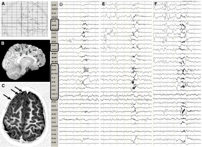
Stereotactic scheme, Post‐implantation and Preoperative MRI, Intracranial Ictal EEG. Patient 7, Table S1. (A) Stereotactic scheme, according to the bicommissural reference system (lateral view), of a right frontal SEEG exploration. Electrodes, labeled by uppercase letters, are indicated with either circles or dotted lines, depending on the orthogonal or oblique trajectory of the implantation. (B) Post‐implantation sagittal T1‐weighted MRI showing the exact position of each electrode. Electrodes appear as either circles or lines depending on the orthogonal or oblique trajectory of the implantation and are labeled as in the stereotactic scheme. (C) Preoperative axial T1‐weighted MRI showing a right frontal anterior area of cortical thickening and abnormal folding consistent with FCD (black arrows). (D,E,F) Intracranial ictal EEG recordings during three clusters of spasms. Electrodes exploring the lesion (i.e. electrodes H, F, R, J and L; black rectangles) are always involved by initial ictal activity at spasm onset. Conversely, no consistent pattern of spread is recognizable. Electrodes are labeled as in the stereotactic scheme and postimplantation MRI. FCD, focal cortical dysplasia; MRI, magnetic resonance imaging.