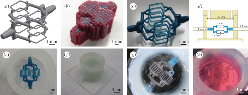
Figure 1.
Process steps for converting CAD model into hydrogel channels. (a) CAD design, consisting of 1 mm inlet symmetrically bifurcating to sixteen 200–250 µm channel features. Each of the finest channels is 2 mm in length. (b) Using a Solidscape 3D printer, models are produced in support wax. (c) Support wax is removed using a selective solvent to reveal a high precision thermoplastic model. (d) Schematic of custom-made silicone chamber; consisting of a silicone sheet mounted on a glass imaging slide, thick-walled silicone tubing for chamber walls, flexible silicone tubing for inlets, and a CNC-milled silicone lid, which has two holes for casting. Also shown is the 3D printed model from (a) for size comparison. (e) Model is mounted into silicone chamber. (f) Chamber is filled with alginate hydrogel and a lid is fitted to the chamber. (g) Following model removal with heat and acetone, gelatin is infiltrated into the channels, and the alginate is removed by chelation. (h) Gelatin template is cast in collagen (shown here) or fibrin hydrogel, which can be loaded with cells prior to gelation.

