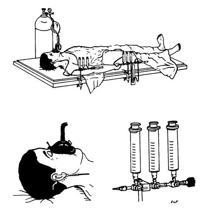
Figure 2.
Experimental set-up for cerebral blood flow determination. Position of needles in internal jugular is shown as well as plastic tubing, manifolds, sampling and flushing syringes, and inhalation system. Mean arterial blood pressure is read from a mercury manometer attached to the arterial manifold. Only the expiratory valve on the mask is shown, the inspiratory valve is between the fluted tubing and the mask. Drawings by Dr. E. L. Foltz. Figure and legend reprinted from ref. 7.

