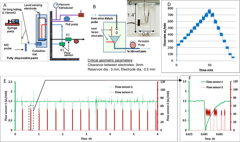
Fig. 2.

A) Schematic of push-pull system with level sensing mechanism. B,C) Detailed schematic of level sensing unit. D) Plot showing flow through the probe can be controlled in steps of 50 nL/min. E) Flow characteristics for push-pull system from a test with 100 kDa probe (1 m tubing before and after probe, 0.125 mm ID, Ringer’s solution) F) Zoomed in data for flowsensor-2, showing four distinct drawing of sample(15,10,2.5,2.5 μL) from the collection vial by the peristaltic pump after the level sensor triggering. Flow sensor-1 shows a dip due to release of vacuum before the withdrawal process.
