
Figure 1.
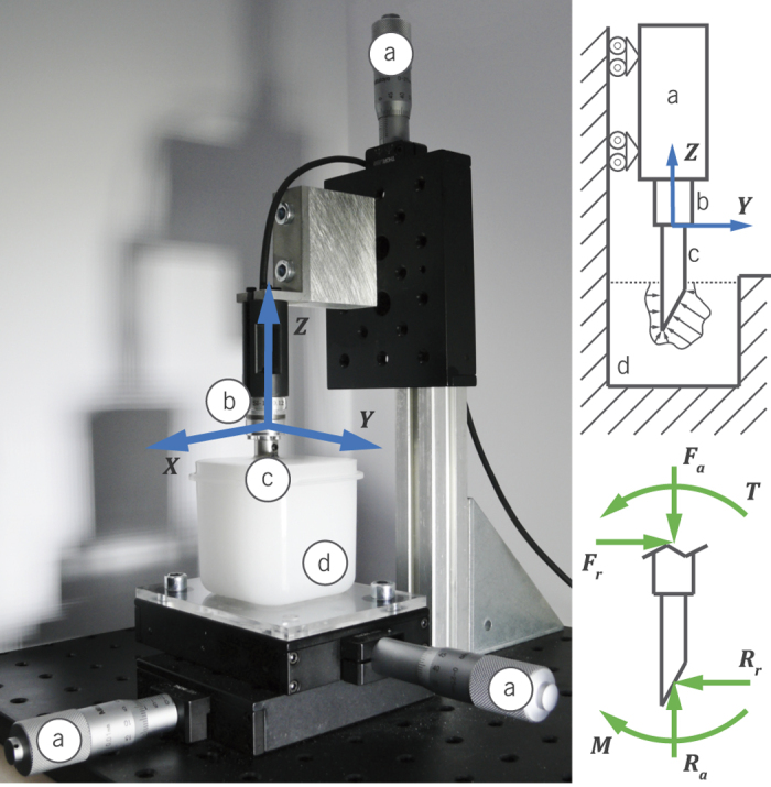
Experimental setup showing (a) the manual stages, (b) the force sensor with global coordinate system, (c) the needle tip, and (d) the tissue phantom. On the right, a schematic mechanical representation of the measurement is shown, including the axial and radial forces, Ra and Rr, and the resultant moment M, at the tip.