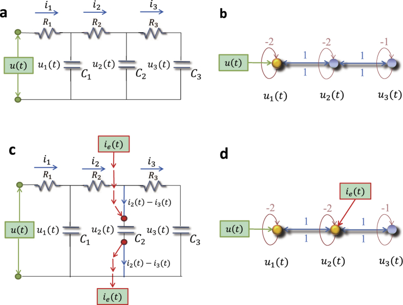
Figure 7. Controlling and optimizing a cascade parallel RC circuit system and the corresponding network presentation.
(a) A cascade parallel R-C circuit with 3 resistors (R1, R2, and R3, each of resistance 1Ω) and 3 capacitors (C1, C2, and C3, each of capacitance 1F), where u(t) is the external input voltage, u1(t), u2(t), and u3(t) are the voltages on the capacitors C1, C2, and C3, and i1(t), i2(t), and i3(t) are the currents through the resistors R1, R2, and R3, respectively. (b) Network representation of the circuit in (a). (c) Circuit with an extra external current input ie(t) into the capacitor C2. (d) The extra external current input ie(t) serves as a redundant control input injected into node 2 of the network in (b). There are two driver nodes (yellow) in the network: 1 and 2.

