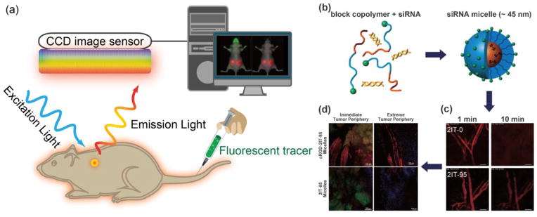
Fig. 4. Optical fluorescence imaging.
(a) A schematic illustration of the basic principle of in vivo fluorescence imaging. First, a fluorescently labeled RNAi therapeutics is injected into mouse body, and the subject is illuminated by an excitation light at specific wavelength, resulting an excitation of fluorescent molecules and subsequent emission light of different wavelength. The emitted light is filtered and then detected by CCD image sensor. The fluorescence signals and animal photo are finally converted to a single detailed image. The figures on right show using fluorescence imaging to trace polymeric micelles incorporated with dye labeled siRNA in the mice body. (b) Schematic illustration of polymeric micelle structure formed by self-assembly of block copolymers with fluorescent dye labeled siRNA. (c) Ear-lobe dermis snap-shots of blood circulation of two types of micelles after intravenous injection for 1 and 10 min. (d) Micro distribution of micelles incorporated with Cy5-labeled siRNA at 24 h post-injection. (red: siRNA; green: tumor cell nuclei; purple: other cell nuclei). Figures adapted with permission from [110].

