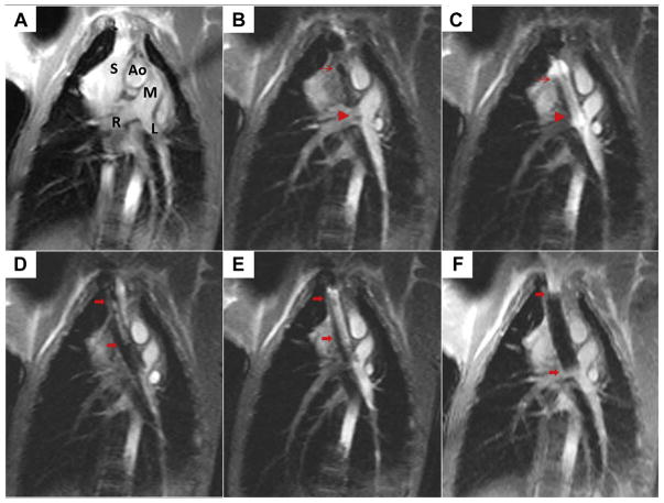
FIGURE 4. Creating the Cavopulmonary Shunt Using Real-Time Magnetic Resonance Imaging.
(A) This oblique coronal working view is shown. Ao = aorta; L = left pulmonary artery; M = main pulmonary artery; R = right pulmonary artery; S = superior vena cava. (B) The first of 2 endografts is positioned across the wall of the pulmonary artery (thin red arrow, proximal endograft; red arrowhead, distal endograft) to allow bidirectional pulmonary blood flow. (C) The first endograft is expanded using a balloon filled with gadolinium contrast. (D) The second overlapping endograft, used for want of a longer single device, is positioned to anchor cavopulmonary conduit in the superior vena cava and exclude the azygos vein (thick red arrows, proximal, distal endograft). (E) The second endograft is deployed. (F) Afterward, the completed percutaneous bidirectional cavopulmonary shunt is visible using real-time magnetic resonance imaging, where it appears black.

