Figure 1.
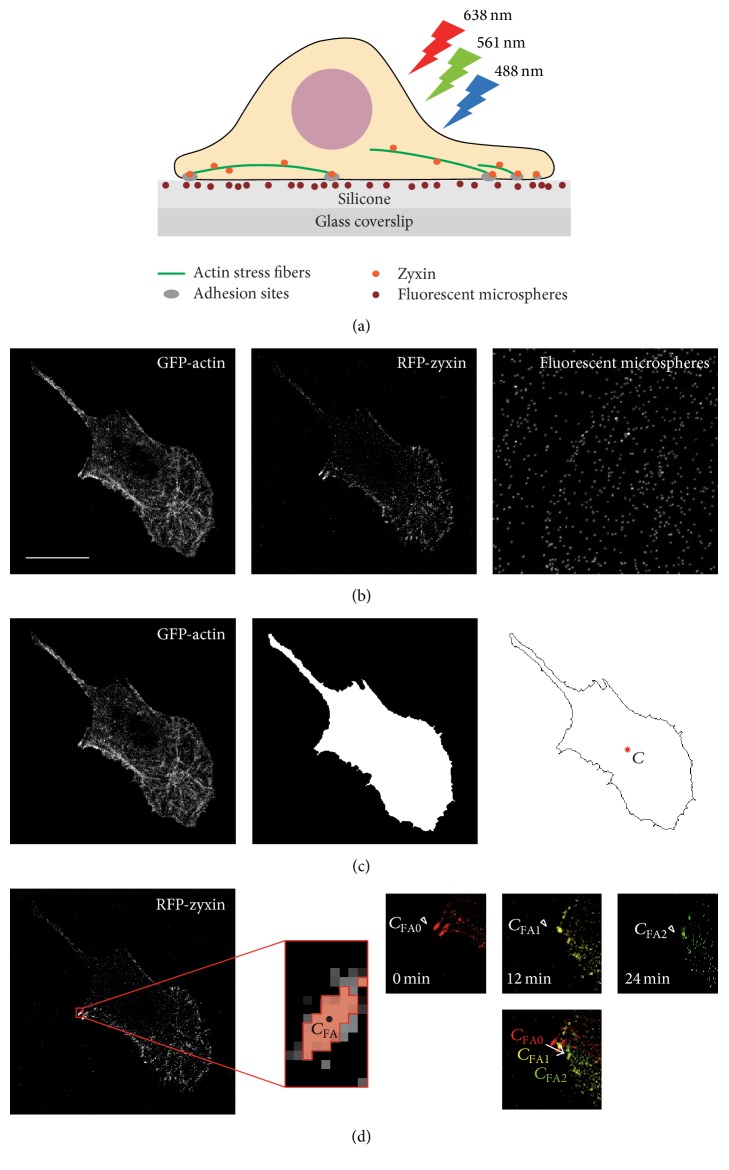
Schematics of image acquisition and processing. (a) Swiss 3T3 fibroblasts expressing GFP-actin and RFP-zyxin were plated on a silicone substrate in which fluorescent dark red microspheres were embedded. GFP, RFP, and dark red microspheres were excited by lasers at 488, 561, and 638 nm, respectively. (b) Examples of maximum intensity projection (MIP) images of GFP-actin, RFP-zyxin, and fluorescent dark red microspheres at time t = 0 minutes. In this case, the MIP images of GFP-actin and RFP-zyxin were created from images #7 (z = 1.2 μm) to #11 (z = 2.0 μm), whereas the MIP image of fluorescent microspheres was created from the images #1 (z = 0 μm) to #5 (z = 0.8 μm). Scale bars: 20 μm. (c) Image processing to identify the cell edge from an MIP image of GFP-actin. The position of the area centroid C is represented by a red asterisk. (d) Image processing for the identification of FAs from an MIP image of RFP-zyxin. Enlarged image around an FA cropped from the MIP image of RFP-zyxin is shown. The image is binarized locally, and the FA area with the area centroid C FA is shown in red with a black dot. Relocation of the FA is shown on the right. In this example, from 0 to 24 minutes, the position of the area centroid of the FA changed from C FA0 to C FA2.

